p 42/58
Technical Manual NAM-BL4x-MT-EN-C
The information in this document is the property of Automatic Systems and is confidential. The consignee withholds from using it for anything other than the use of the products or the execution of the
project to which they belong and withholds from communicating it to third parties without prior written agreement from Automatic Systems. Document subject to change without prior notice.
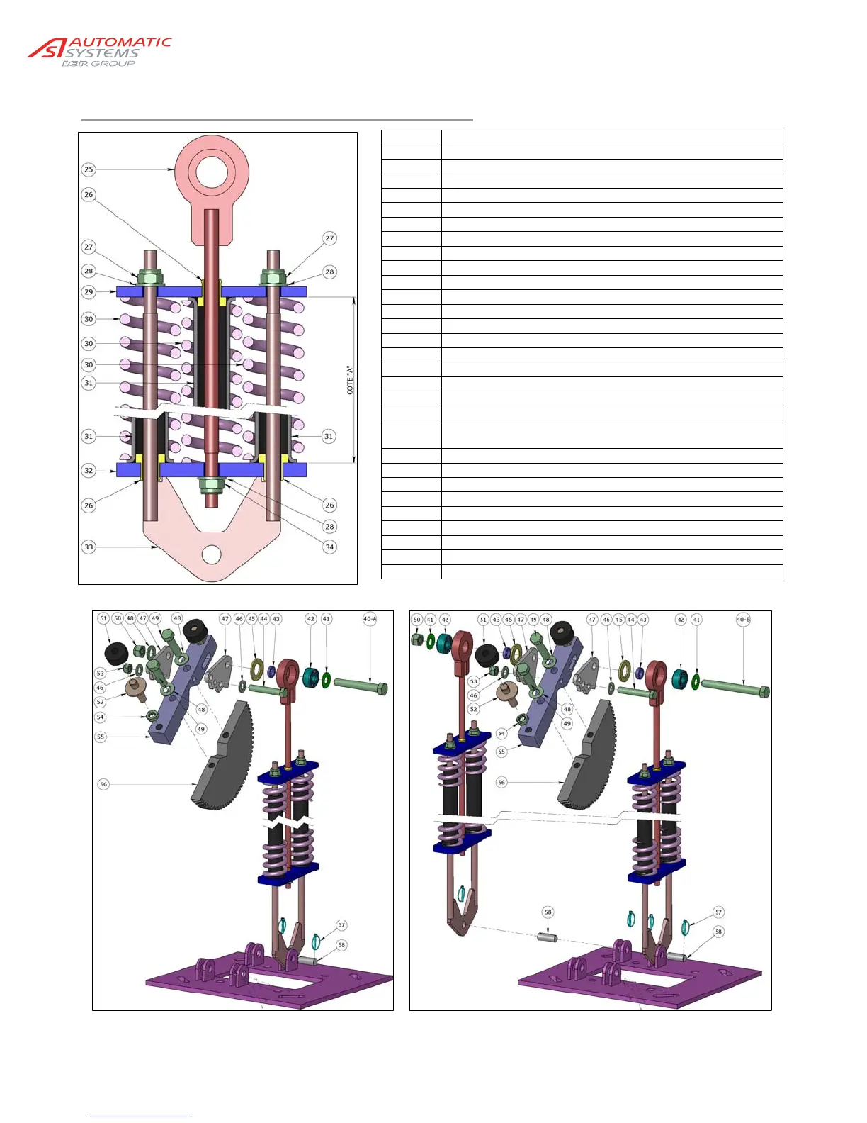
5.2. Adjusting the balancing springs
Detail of s
rin
assembl
Mounting of a spring assembly (1 to 3 springs) Mounting of 2 spring asemblies (4 to 6 springs)
25 Central rod
26 Guide bushing
27 Nylstop M16 nut (steel)
28 M 16 flat washer (steel)
29 Upper flange plate
30 Compression spring
31 Guiding tube
32 Lower flange plate
33 Double rod
34 Nylstop M16 nut (steel)
40-A H M20x140 NF EN 24014 screw (steel)
40-B H M20x180 NF EN 24014 screw (steel)
41 Bearing stop
42 3304B bearing with 2 rows of balls
43 Steel spacer
44 H M16x100 screw (steel)
45 Nylon washer
46 M 16 flat washer (steel)
47 Eccentric for adjustment of spring (x2 per barrier)
48 M 20 flat washer (steel)
49 H M20x80 NF EN 24014 screw (steel)
(tighten to 190Nm)
50 Nylstop M20 nut (steel)
51 = 10
Rubber bumper (x2 per barrier)
52 M20 stop (x2 if no locking of arm option)
53 Nylstop M16 nut (steel)
54 Hm M20 nut (steel) (x2 per barrier)
55 Hub
56 Sector gear
57 Locking pin, Ø 4.5
58 Spring pin