p 43/58
Technical Manual NAM-BL4x-MT-EN-C
The information in this document is the property of Automatic Systems and is confidential. The consignee withholds from using it for anything other than the use of the products or the execution of the
project to which they belong and withholds from communicating it to third parties without prior written agreement from Automatic Systems. Document subject to change without prior notice.
For operation without automatic lifting the arm in the event of power outages, the tension in the spring must
be adjusted so as to ensure minimum stress on the motor when opening and closing the barrier:
Slightly lift the arm then release it: it must stay balanced.
Repeat the operation for the arm’s various angular positions.
If the arm falls down, the spring compression must be increased.
If the arm rises, the spring compression must be decreased.
For operation with automatic lifting of the
arm in the event of power outages, the springs must slowly and fully
lift the arm, up to its vertical position. Contact between the rubber bumper (51) and the frame should not be
too violent, as this may lead to rapid deterioration.
If the arm does not open completely, the spring compression must be increased.
If the arm rises too quickly, the spring compression must be decreased.
Adjusting the spring compression:
1. Tighten or loosen the screws (27) to increase or decrease, respectively, spring compression.
Warning
: Plates (29) and (32) must remain parallel and the distance between them (rating A) may
not be smaller than 444 mm in order for the springs not to deteriorate.
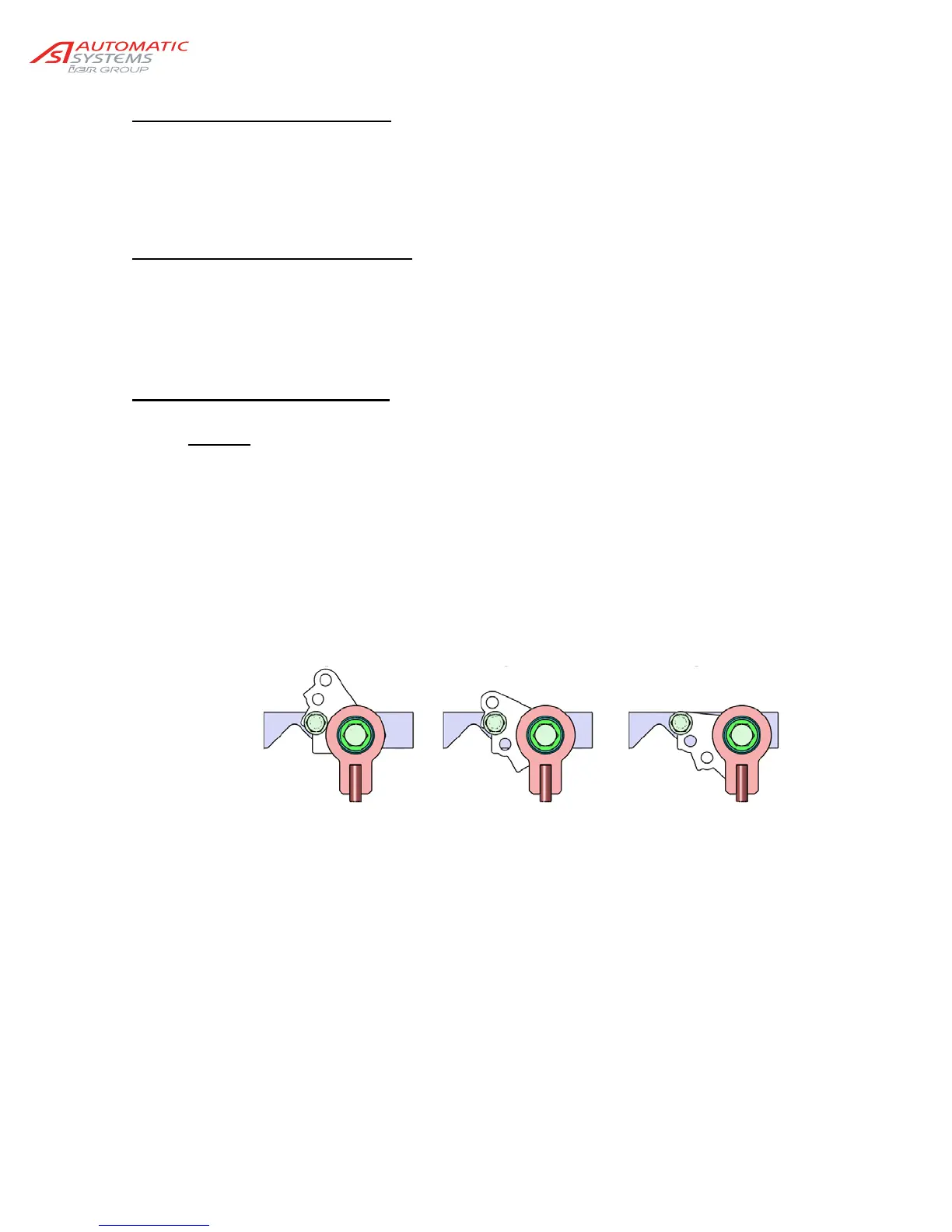
2. If this adjustment proves to be insufficient, change the assembly of the eccentrics (47):
a. Bring the arm to the vertical position.
b. Switch the equipment off by turning off the circuit breaker (20).
c. Release the central spring rods (40) by loosening the screw a few turns (50).
d. Completely remove the screw (44) making sure not to drop the washer plates (46) as well as
the nut (53).
e. Place the eccentrics (47) in the hub (55) in accordance with the desired configuration:
f. Put the screw (44), washers (46) and the nut (53) back.
g. Retighten the screw (50).
3. If the adjustment is still insufficient, increase or decrease the number of springs.
The following table provides an indication of spring adjustments for the various arm lengths.
A
Min. lever arm
=> Min. compression
B
C
Max. Lever arm
=> Max. compression