p 44/58
Technical Manual NAM-BL4x-MT-EN-C
The information in this document is the property of Automatic Systems and is confidential. The consignee withholds from using it for anything other than the use of the products or the execution of the
project to which they belong and withholds from communicating it to third parties without prior written agreement from Automatic Systems. Document subject to change without prior notice.
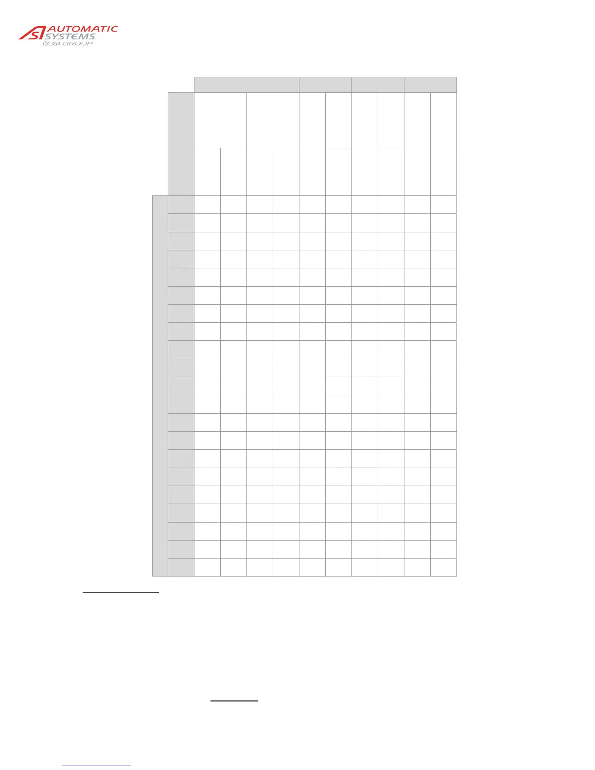
TABLE OF THE PRINCIPAL SPRING ADJUSTMENTS
BL 40 BL 41 BL 43 BL 46
Options
Without
lifting of the
arm
With lifting
of the arm
Without
lifting of the
arm
With lifting
of the arm
Without
lifting of the
arm
With lifting
of the arm
Without
lifting of the
arm
With lifting
of the arm
Bare arm
Aluminium
netting
Bare arm
Aluminium
netting
Bare arm
Bare arm
Bare arm
Bare arm
Bare arm
Bare arm
Useful length (m)
2
1-B-
586
2-A-
606
1-B-
590
2-A-
608
2,5
2-A-
610
2-A-
584
2-A-
602
2-A-
574
3
2-A-
586
2-B-
606
2-B-
606
3-A-
598
3,5
2-B-
604
3-A-
596
3-A-
586
3-B-
610
4
1-B-
604
2-A-
598
2-A-
610
2-B-
610
2-A-
610
2-A-
582
3-A-
592
3-B-
610
3-B-
608
3-B-
592
4,5
1-B-
586
2-A-
572
2-A-
604
2-B-
594
2-A-
596
2-B-
610
3-B-
610
3-B-
596
4-A-
580
4-B-
610
5
1-C-
606
2-B-
594
2-A-
588
3-A-
588
2-A-
582
2-B-
602
4-A-
586
3-C-
610
4-B-
594
5-A-
572
5,5
2-A-
600
3-A-
586
2-B-
610
3-B-
610
2-B-
610
3-A-
602
4-B-
610
4-B-
598
5-B-
606
5-B-
596
6
2-A-
582
3-B-
610
2-B-
602
3-B-
592
2-B-
592
3-A-
586
5-A-
576
5-B-
610
6-B-
610
6-B-
602
6,5
2-A-
570
3-B-
592
3-A-
606
3-C-
610
3-A-
598
3-A-
578
6-B-
592
6-B-
586
7
2-B-
594
4-B-
568
3-A-
588
4-B-
602
3-A-
570
3-B-
600
6-C-
610
6-C-
610
7,5
3-A-
598
4-B-
598
3-A-
580
5-B-
610
3-B-
608
3-B-
592
8
3-A-
588
4-B-
586
3-B-
610
5-B-
600
3-B-
600
3-C-
610
8,5
3-B-
590
3-C-
610
9
4-A-
580
4-B-
610
9,5
4-A-
570
4-B-
604
10
4-B-
608
4-B-
596
10,5
4-B-
598
5-A-
576
11
5-A-
572
5-B-
606
11,5
5-B-
610
5-B-
600
12
5-B-
602
6-B-
610
Reading the table
Column: barrier model with options.
Line: useful length of the arm (distance from the tip of the arm to the housing, see Ch. 8. ).
Intersection: "X-Y-Z", where
X = number of useful springs
Y = position of the eccentric (n°47, see above)
Z = compression of the springs, in mm
= distance between plates (29) and (32)
= rating A.
WARNING
: when the barrier is closed (arm lowered), the compressed springs
length must not be under 444 mm!