p 6/58
Technical Manual NAM-BL4x-MT-EN-C
The information in this document is the property of Automatic Systems and is confidential. The consignee withholds from using it for anything other than the use of the products or the execution of the
project to which they belong and withholds from communicating it to third parties without prior written agreement from Automatic Systems. Document subject to change without prior notice.
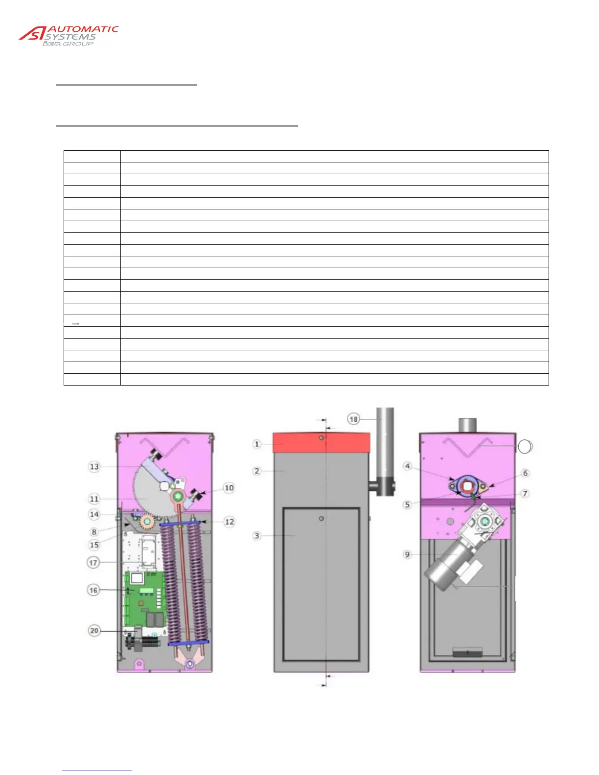
2. DESCRIPTION
2.1. Location of the components
1 Cover, locked with two locks and keys
2 Housing
3 Front door, locked by lock and key
4 Bearing for main shaft (x2 per barrier)
5 Detection cam (x2 per barrier)
6 Bracket for inductive sensors
7 Inductive position sensor (x2 per barrier)
8 Protective cover
9 Gear motor
10 Bumper (x2 per barrier)
11 Sector gear
12 Spring assembly (x1 or x2 per barrier) (see Ch. 0)
13 Hub
14 Plummer block
15 Pinion
16 Control board
17 Variable speed controller
18 Arm
19 Reinforcing V-block, optional arm locking support
20 Circuit breaker
19