p 49/58
Technical Manual NAM-BL4x-MT-EN-C
The information in this document is the property of Automatic Systems and is confidential. The consignee withholds from using it for anything other than the use of the products or the execution of the
project to which they belong and withholds from communicating it to third parties without prior written agreement from Automatic Systems. Document subject to change without prior notice.
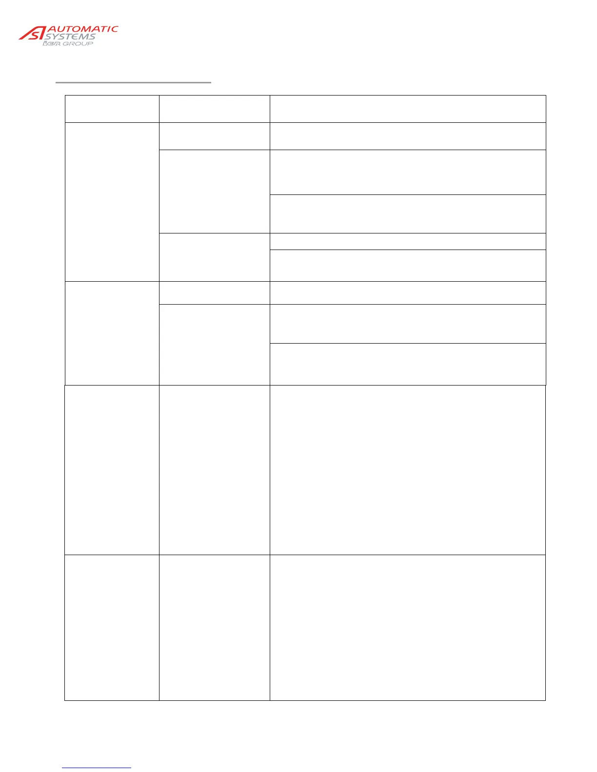
6.6. Troubleshooting
SYMPTOM
CAUSE
APPROPRIATE SOLUTIONS
The barrier stays
open
Open command is
given continually
Check that the open command is a pulse and not a
continual command.
The loop sensor
(optional) remains
engaged
Review the sensor’s sensitivity adjustment and reset the loop
sensor to zero. Adjusting the sensitivity adjustment to a setting
that is too high may lead to locking in the open position.
Check the condition of the LEDs on the detector to see
whether it and/or the loop are in good condition.
The cell (optional)
sends information that
something is present
Check the alignment of the cells.
Check that the cells are not dirty.
The barrier stays
locked, or locks
during movement
The variable speed
controller is defective
See the list of defects regarding the variable speed controller.
The limit switch
sensor provides
incorrect information
(see Ch.5.3. )
In the horizontal position: ensure that the horizontal
position sensor is the only one to be in the cam’s cut-out
and that it is operational and connected correctly.
In the upright position: ensure that the upright position
sensor is the only one to be in the cam’s cut-out and that it
is operational and connected correctly.
The barrier stays
locked and the
display on the
control board is off
Power supply
Check the power supply at the general power supply box.
Check the current voltage at the entry of the cable to the
general circuit breaker (20, Ch. 2.1. ), and ensure that the
latter is engaged (circuit breaker at ON).
Check the command connections in accordance with the
wiring diagram as well as the correct tightening of all
electrical cables and tighten, where necessary.
Check the condition of the two fuses on the control board.
If the 5 green LEDs near the LCD are lit, check whether the
control board is in programming mode (cable RJ45 is
connected).
The barrier stays
locked, but the
control board display
is lit
Short circuit on the
external communication
terminal block
Check whether the red LEDs near the LCD (other than
analogue output) are lit.
- If not, switch off the mains supply and remove the
terminal blocks (on the AS1320 and AS1321 if present).
Switch the power back on and check again whether the
red LEDs are lit. If this is the case, a short circuit is
present in the terminal blocks. In order to reactivate
the outputs, the control board has to be turned on again.
- If so, see the defects displayed (PRDSTD – BL_xxx
menu Log/ Close status/Open status).