p 55/58
Technical Manual NAM-BL4x-MT-EN-C
The information in this document is the property of Automatic Systems and is confidential. The consignee withholds from using it for anything other than the use of the products or the execution of the
project to which they belong and withholds from communicating it to third parties without prior written agreement from Automatic Systems. Document subject to change without prior notice.
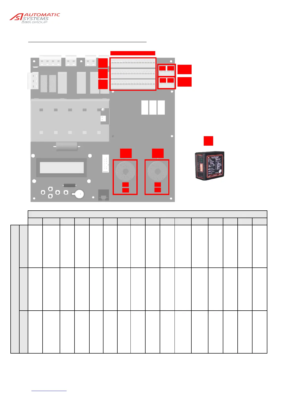
9.1. Control blocks assignment
Connector block number
1 2 3 4 5 6 7 8 9 10 11 12 13 14 15 16
Connectors
A
GND
GND
GND
GND
24V
24V
24V
GND
GND
GND
REL3 -
Output relay 3
REL3 +
Output relay 3
GND
GND
GND
GND
B
AO1
FI setting
DO11 PWM
Output 11
DO8
Descending motor
24V
DI13
Closing LS
DI11
Lock Close CMD
DI9
Close command
24V
24 V
24V
REL2 -
Output relay 2
REL2 +
Output relay 2
24V
24V
24V
24V
C
AI1
Analog. Sensor
DO10sPWM
Output 10
DO7
Rising motor
DI14
crank limit switch
DI12
Opening LS
DI10
Lock Open CMD
DI8
Open command
DI7
Stop command
DI6
Reader A command
DI5
Swing off sens./Lock
REL1 -
Output relay 1
REL1 +
Output relay 1
DI4
Cell 4
DI3
Cell 3
DI2
Cell 2
DI1
Cell 1
A In/Out
B connector blocks.
C
X13 Inductive loops
X14 connectors.
X9 Connectors for
X11 inductive loops
presence detectors.
Y Inductive loops
presence detector.
A
B
C
1 2 3 4 5 6 ............................
X14
X11
DP1DP2
DP3DP4
Y
DP1
DP2
DP3
DP4
X13
X9