p 45/58
Technical Manual NAM-BL4x-MT-EN-C
The information in this document is the property of Automatic Systems and is confidential. The consignee withholds from using it for anything other than the use of the products or the execution of the
project to which they belong and withholds from communicating it to third parties without prior written agreement from Automatic Systems. Document subject to change without prior notice.
5.3. Adjusting the position sensors
The aim of the position sensors is to stop the opening and closing movement of the arm.
Each movement (opening and closing) is controlled by its own inductive sensor, of the discrete type.
The passage of the cut-out of the cam in front of the sensor results in the power being cut to the motor, the
activation of the electromagnetic brake and the activation or release of the arm’s optional locking system
(depending on whether the lock is NO or NC).
The sensors are adjusted correctly if the motor stops exactly when the bumper (10, Ch. 2.1. ) comes into
contact with the frame’s reinforcing V-block (19), both during opening and closing.
To do so:
- Bring the arm to the horizontal position (closed).
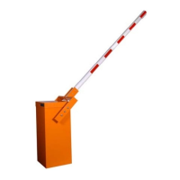
- Loosen the screw locking the cam in the horizontal position and slightly pivot the latter on the
shaft, until the LED on the sensor turns off (= detection of cam’s groove). Pivot the cam by a few
additional degrees.
- Bring the arm to the upright position (open) and repeat the operation with the upper position cam.
Motor is activate
earlie
Motor is activate
late
Motor is activated
earlier
Motor is activated
later
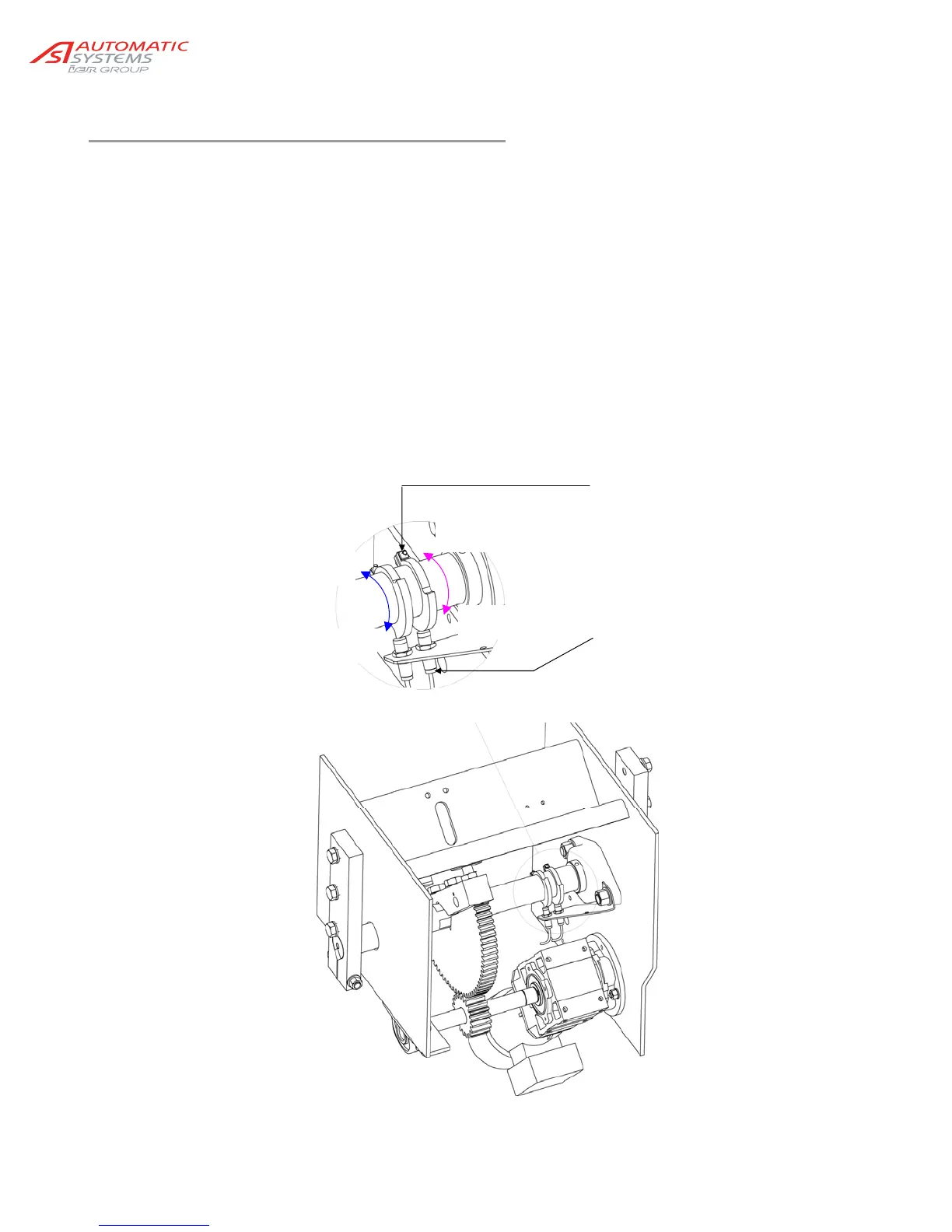
Cam & sensor in the horizontal
position (closest to the bearing)
Cam & sensor in the upright
position
Screw locking the cam
LED lit when the sensor is in detection mode