p 29/58
Technical Manual NAM-BL4x-MT-EN-C
The information in this document is the property of Automatic Systems and is confidential. The consignee withholds from using it for anything other than the use of the products or the execution of the
project to which they belong and withholds from communicating it to third parties without prior written agreement from Automatic Systems. Document subject to change without prior notice.
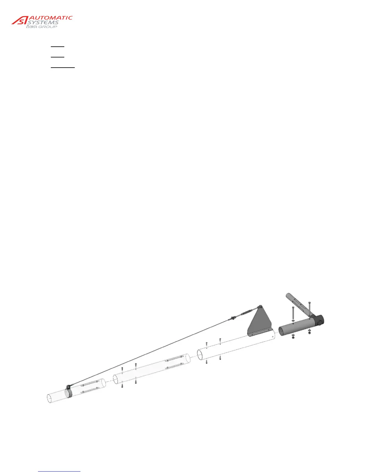
Note: All screws must be lubricated before assembly.
Note
: Minimum tightening torques are provided in the illustration’s legend.
Warning
: In the event of removing the arm assembly, the spring assemblies’ lower fastening pin (57) must be
removed beforehand, in order to release the tension in the springs.
1. Turn off the power to the barrier by turning off the circuit breaker (20, Ch. 2.1. ).
2. Unlock the nut (54) and screw the upper bumper (10) as far as possible into the hub (13), in order to
remove the compression constraint on the springs (30), then lift the shaft (77).
3. Remove the spring assembly’s lower hinge pin (57).
4. Slowly lower the arm stirrup. If the barrier is equipped with the mechanical locking unlock the system
first by pulling on the electromagnet shank.
5. Place the first arm coupler (71) on the arm rotating shaft (77).
Tighten the screws (74), washers (75) and nuts (76).
Place the second arm coupler (72), if any, in the first one and tighten the screws (70).
Place the third arm coupler (72), if any, in the second one and tighten the screws (70).
6. Lift the arm, if needed, unlock the system.
7. Replace the spring assembly’s lower fastening axle and lock it using its pin (57).
8. Adjust the verticality of the arm by tightening or loosening the upper bumper (10), then tighten the
lock nut (54).
9. Fasten and, where necessary, tighten the bracing wire (see illustration on the folding fence, below).