10
AM800, AM808 & AM888 Dominator Instruction Manual
6.2 Mounting Operator for a Track Type Door
43
21.5
21.5
SNAP PIN
PIN
WALL BRACKET
PLACE OPENER ON TOP OF
FABRIC CLOTH OR CARDBOARD BOX
TO AVOID SCRATCHES
Track
Level
Door
Drilled holes
Fig.6.2.3
Fig.6.2.2
Fig.6.2.1
WARNING! To reduce the risk of injury to persons -
Use this operator only with a sectional door.
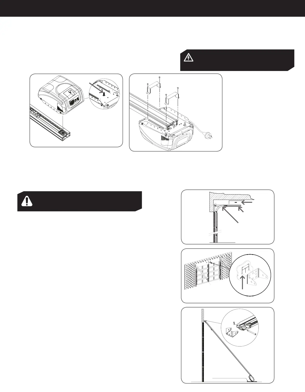
6.1 C-Rail Assembly
6.1.1 Installing the C-Rail
Locate and insert the shaft of drive unit into sprocket as shown in Fig.6.1.
Fix the two track brackets with four screws supplied in accessory pack as
shown in Fig.7.2
Locate shaft into sprocket
Shaft
4 Taptite screws ‘S’ M4 X 10
2 Track brackets VP1
Fig.6.1.2
Fig. 6.1.1
ELECTROCUTION! This operator is not equipped
for permanent wiring. Contact a qualified electrician
to install a suitable receptacle if one is not available.
AM808 / AM888 Model shown
AM808 / AM888 Model shown
6.2.1 Determine Bracket Position
Open the door and find the highest point of travel of the top door panel. Using
a level, transfer this height to the wall above the door (Fig.6.2.1) and mark a line
0.197” (60mm) above it.
Determine the centre point on the wall above and on top of the door. Then draw two
lines 0.0705” (21.5mm) on each side of the centre point (Fig.6.2.2).
6.2.2 Mounting the Wall Bracket
The wall bracket should be mounted 0.197” (60mm) above highest point of the doors
travel, 0.0705” (21.5mm) from the centre point (Fig.6.2.3).
If the wall bracket is mounted onto concrete or brick wall, use 8mm or 5/6 loxins or
dynabolts. If mounting onto wooden lintel or beam, use wood screw #20 or equivalent
(minimum 1.97” (50mm) long).
WARNING!: Make sure concrete, brick wall or timber lintels are solid and sound so
as to form a secure mounting platform.
6.2.3 Attach the C-Rail to the Wall Bracket
When the wall bracket is firmly secured in its proper position, attach the C-Rail
support assembly to wall bracket with 0.295” (90mm) long clevis pin and secure with
supplied snap pin (Fig.6.2.3).
Leave the drive unit in its packing box for protection during installation.