Diamond PD Power Drive : Instruction Manual
Dominator Instruction Manual AM800, AM808 & AM888
11
© Copyright 2017
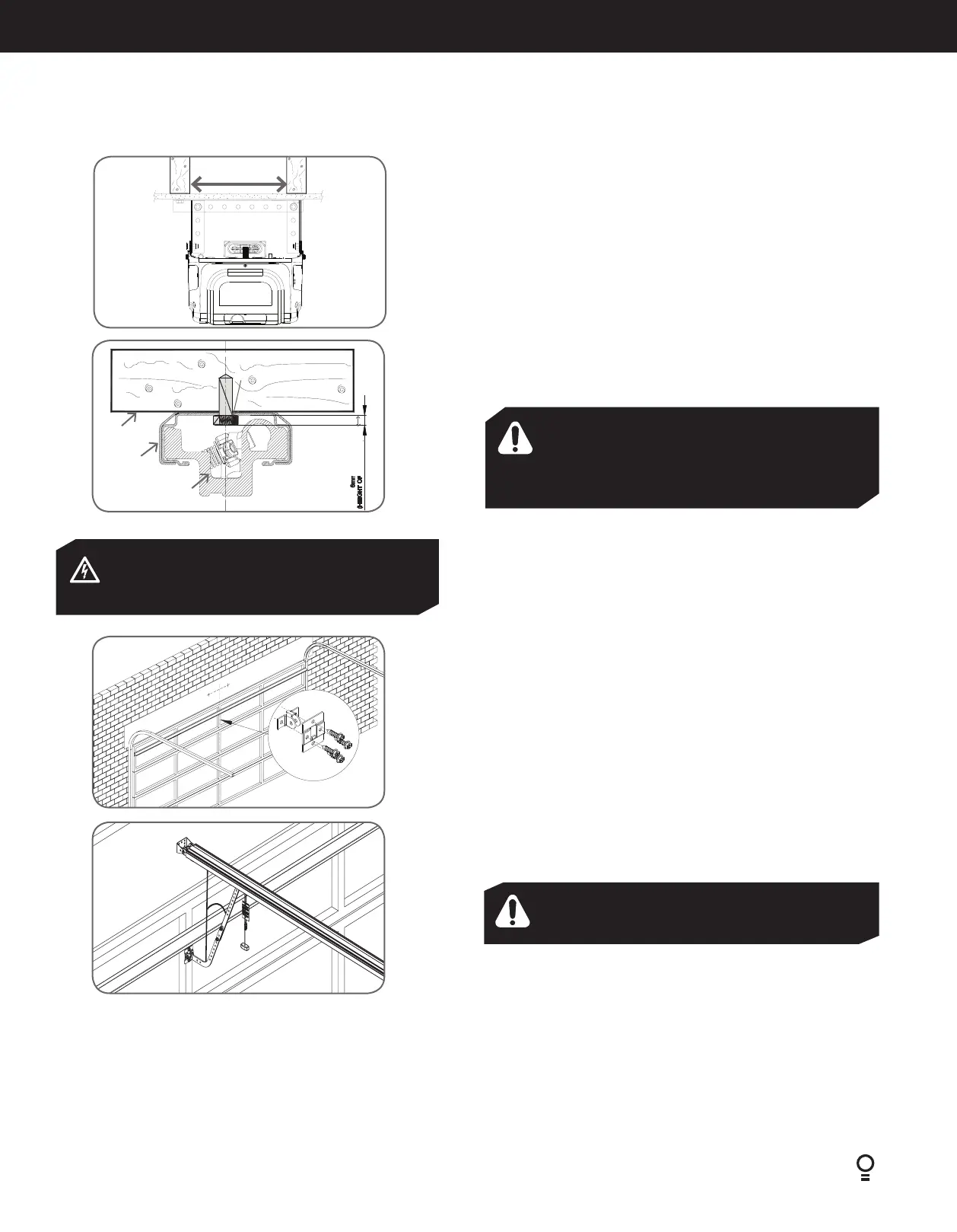
Structural member
Fig.6.2.4
WARNING! The operator must be securely fastened
to a structural support of the garage. Failure to fasten
the operator correctly may lead to operator failure
causing serious personal injury and/or property
damage.
ELECTROCUTION! This operator is not equipped
for permanent wiring. Contact a qualified electrician
to install a suitable receptacle if one is not available.
6.2.4 Securing the Powerhead to the Ceiling
Raise the drive unit from the packing box and support it in a horizontal
position with a step ladder, then open the garage door. Rest the operator on
the open door and use a scrap piece of wood to bring it to horizontal level.
Line up the track perpendicular to the wall.
Secure the perforated angle (not supplied) to the ceiling above where drive
unit mounting holes will be once fully installed (Fig.6.2.4).
Connect angle and drive unit with two flat perforated strips of angle (not
supplied) with M8 x 20mm screws, and nuts. Strips should not extend more
than 0.059” (18mm) below centre of drive unit mounting holes (Fig.6.2.4).
6.2.5 Alternative Mounting Option
The operator can be fastened to the roof by drilling a hole in the centre of the
C-Rail and driving a bolt through it into structural timber support. The height
of bolt head must not exceed 0.24” (6mm) (Fig.6.2.5).
Ceiling
Aluminium rail
Shuttle VP2 assembly
Drill hole at centre of
track (recommended
bolt size M6 or M8)
The height
of bolt head
must not
exceed 6 mm
Fig.6.2.5
Fig.6.2.6
Fig.6.2.7
6.2.6 Mounting Door Bracket
The door bracket comes in two parts. The bottom plate with two mounting
holes is used on its own for any one piece doors. The top plate is placed over
the bottom plate and uses 4 mounting holes for extra strength. This is used
on sectional doors (Fig.6.2.6).
Mount the door bracket to the centre line of the door, 1/3 panel down using
M6 or equivalent screws (not supplied) alternatively it can be welded on steel
doors.
NOTE: As various types of doors exist, if in doubt about the strength of the
door, reinforcement may need to be added to the frame of the door panel
where necessary. Damage to the door panel may occur if the bracket is
installed incorrectly on a panel with insufficient strength. The door operator
warranty does not cover damage caused by the operator to the door and/
or door panel.
6.2.7 Attaching the Arms
Assemble bent and straight arms (as shown in Fig.6.2.7) with bolts and nuts
supplied in accessory pack. Then connect assembled arm to the door bracket
and the trolley by clevis pin and snap pin. Trolley must be in disengage
position. Always use both the bent and straight arm.
The angle “A“ must not be less than 10 degrees.
WARNING! connecting the bent arm other way around
may damage the door.
IMPORTANT NOTE: If the manual release handle is more
than 5.91ft (1.8 meters) from floor level when the operator is
installed, extend the handle to a height 5.91ft (1.8 meters).
A
6.2 Mounting Operator for a Track Type Door