Chapter 5: Additional Operational Information 55
Using Video Inputs with VITC and the Character
Generator
Unlike selecting a video input to use for Clock
Reference, input selection for VITC and character
generator functions follows a simple rule. This rule
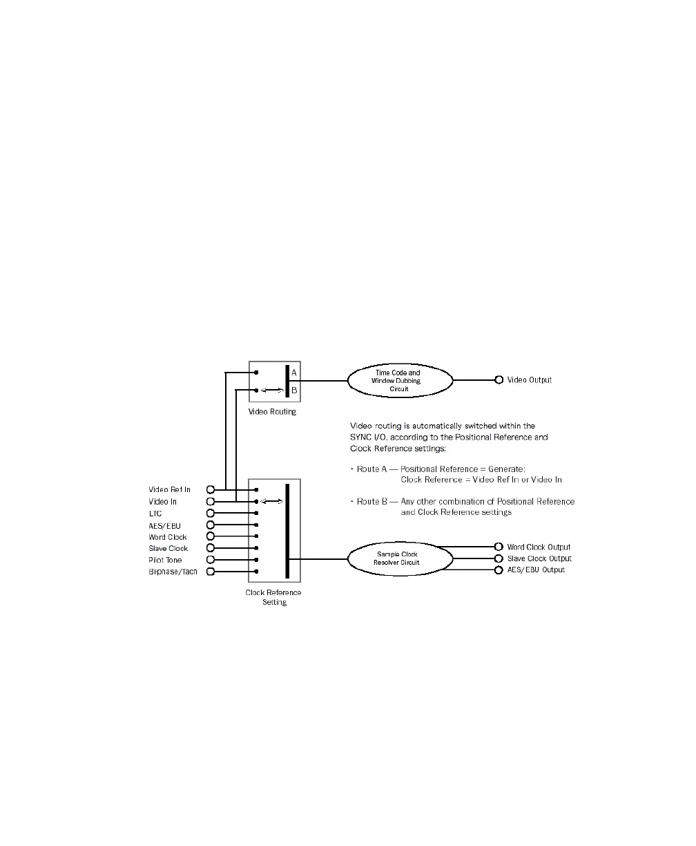
is explained in the following sections and in
Figure 3 on page 55.
Video Ref
If the Clock Reference is one of the two
video inputs, and the Positional Reference is Gen-
erate, then VITC and character generator functions
are applied to the video arriving at the Video Ref
input connector. This helps you avoid re-patching
video cables whenever you want to stripe a video-
tape with your reference blackburst or color bars,
along with internally generated time addresses for
VITC (and/or LTC, and/or CG dub window). In
Figure 3 on page 55, this scenario is identical to
“Route A.”
Video In
For all other combinations of Clock Ref-
erence and Positional Reference, VITC and char-
acter generator functions are applied to the video
signal arriving at the Video In connector. In this
way, the SYNC HD can read VITC from your vid-
eotape, or add VITC with or without character gen-
eration (window burn) while dubbing to a second
VCR. In Figure 3 on page 55, this scenario is iden-
tical to “Route B.”
Figure 3. Video Input Flow diagram