84
The two relay pins are galvanically separated
from the rest of the circuitry.
COM 6 Common
12 V DC 7 For powering auxiliary equipment.
Note: This pin can only be used as power out.
Output voltage 12 V DC
Max current 100 mA
3
Max current 700 mA
4
DC ground 8 0 V DC
Reader connector
4–pin terminal block for connecting external reader.
Function Pin Notes Specifications
DC ground 1 0 V DC
12 V DC 2 For powering auxiliary
equipment.
Note: This pin can only
be used as power out.
Output voltage 12 V DC
D0/A+ 3 Wiegand: DATA0 output
RS485: A+
D1/B- 4 Wiegand: DATA1 output
RS485: B-
I/O connector
Use the I/O connector with external devices in combination with, for example, motion detection, event
triggering, and alarm notifications. In addition to the 0 VDC reference point and power (12 V DC output), the I/O
connector provides the interface to:
Digital input - For connecting devices that can toggle between an open and closed circuit, for example PIR
sensors, door/window contacts, and glass break detectors.
Digital output - For connecting external devices such as relays and LEDs. Connected devices can be activated by
the VAPIX® Application Programming Interface, through an event or from the device’s web interface.
Function Pin Notes Specifications
DC ground 1 0 VDC
DC output 2
Can be used to power auxiliary equipment.
Note: This pin can only be used as power out.
12 VDC
Max load = 50 mA
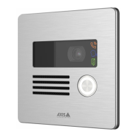
AXIS A8207-VE Mk II Network Video Door Station
3. When powered through Power over Ethernet IEEE 802.3af/802.3at Type 1 Class 3.
4. When powered through Power over Ethernet Plus (PoE+) IEEE 802.3at Type 2 Class 4 or DC power input.

 Loading...