85
Configurable
(Input or
Output)
3–6 Digital input – Connect to pin 1 to activate, or leave
floating (unconnected) to deactivate.
0 to max 30 VDC
Digital output – Internally connected to pin 1 (DC
ground) when active, and floating (unconnected) when
inactive. If used with an inductive load, e.g., a relay,
connect a diode in parallel with the load, to protect
against voltage transients.
0 to max 30 VDC, open
drain, 100 mA
Example:
1 DC ground
2 DC output 12 V, max 50 mA
3 I/O configured as input
4 I/O configured as output
5 Configurable I/O
6 Configurable I/O
Power connector
2-pin terminal block for DC power input. Use a Safety Extra Low Voltage (SELV) compliant limited power source
(LPS) with either a rated output power limited to ≤100 W or a rated output current limited to ≤5 A.
Function Pin Notes Specifications
DC ground 1 0 V DC
DC input 2 For powering controller when not using
Power over Ethernet.
Note: This pin can only be used as power in.
8–28 V DC, max 22 W
Max load on outputs 9 W
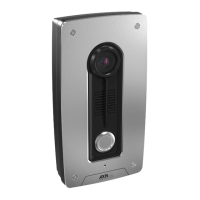
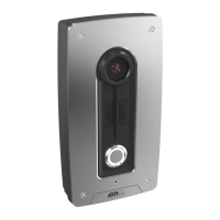
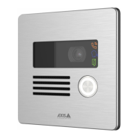
AXIS A8207-VE Mk II Network Video Door Station

 Loading...