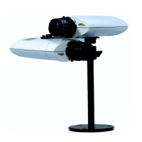
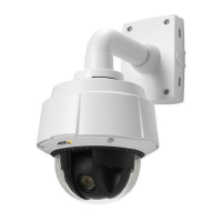
Physical Description AXIS Panorama PTZ User’s Manual
8
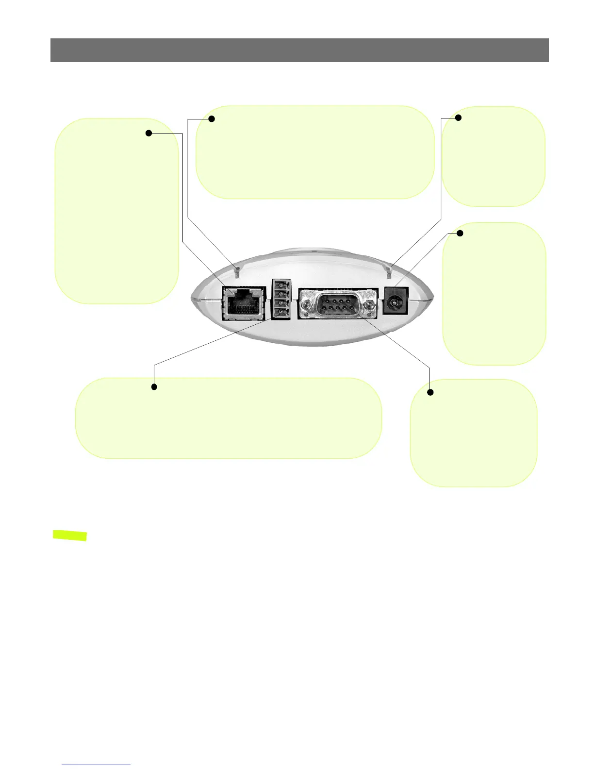
Rear Panel
Note: The power adapter supplied with your AXIS Panorama PTZ is country-specific. Please
check that the type you are using is correct.
Power Supply
Connector
A single Jack socket
(PS-D) for connection
of AXIS Panorama PTZ
power supply. The ter-
minal block connector
provides an auxiliary
connection point for
AC or DC power to the
unit.
Power Indicator
Normally lit when
power is applied. If
not lit, or if flashing,
there is a problem
with the external
power source.
Network Indicator
After completion of the startup and self test routines, this
multi-colored indicator flashes as follows:
• yellow - activity on a 10Mbps network
• green - activity on a 100Mbps network
• red - no physical connection to the network
Network Connector
The AXIS Panorama PTZ
connects 10/100 Mbps
Ethernet networks via a
twisted pair category 5
cable (10baseT and
100baseTX), terminated
using a standard RJ-45
connector. The AXIS Pan-
orama PTZ detects the
speed of the local network
segment and varies the
speed of data communica-
tion accordingly.
I/O Connector
Provides the physical interface to a digital output, and a single digital
photo-coupled input that is used for connecting a variety of external alarm
devices to the AXIS Panorama PTZ; including, IR-sensors, switches and
alarm relays. For more information on using these devices, please see the
AXIS 2110 User’s Manual.
RS-232 Serial
Connector
The serial connector pro-
vides the RS-232 interface
for connecting a modem or
the AXIS 2191 Audio Mod-
ule (these functions are
not supported.)