Initial Assembly
12
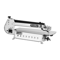
Drive shaft for the tilt mechanism
Hand wheel for the tilt mechanism
Fig 17
Fig 18
Square key
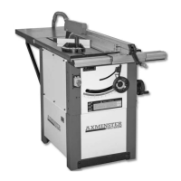
Fitting hand wheel to the rise and full
mechanism
Fig 19
Fig 20
Key slot
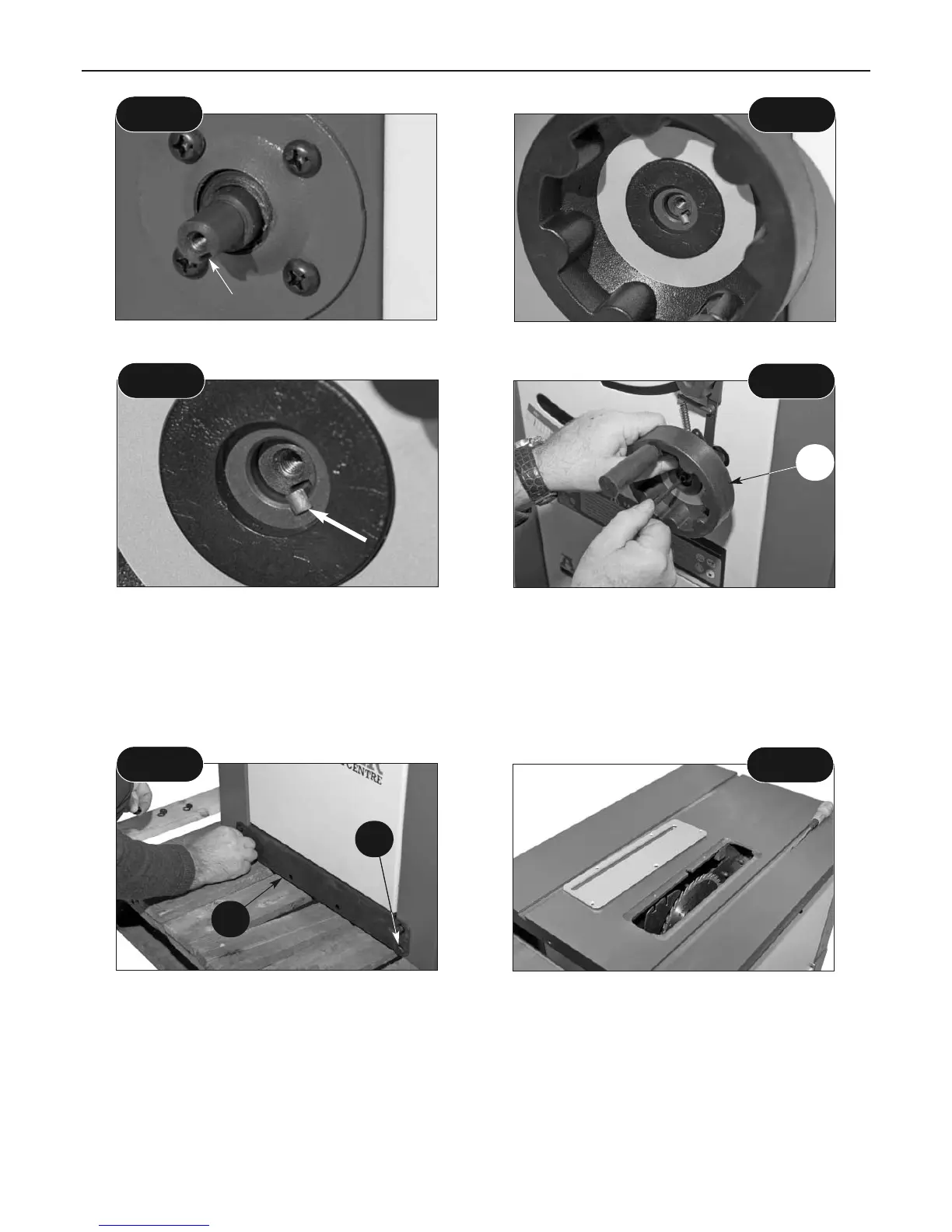
Fig 21
Fig 22
Fitting Kickplate
Locate the kickplate (3A) and 4 No: M8 x 16mm bolts and washers (5C), line-up the
pre-drilled holes in the kickplate with the threaded holes in the lower leg columns (3) and secure
using the bolts and washers. (See fig 21)
10
5C
3A
Saw Guard Assembly
Locate the Riving Knife (14), remove the 5 screws that secure the saw gullet, place both carefully
aside. (See fig 22) Raise the saw blade up to its highest point.
NOTE: The mounting plate for the riving knife has been factory set to ensure that the riving
knife is aligned with the blade. DO NOT alter the setting bolts.
 Loading...