Initial Assembly
18
Locate the long Rip Fence (front rail) (33) and (back rail) (34), remove the short rip fence front and
back rails (22-23) from the saw bench (1), (follow the instruction on pages 14 and 15, “Rip Fence
Assembly” to assemble the long rip fence rails.
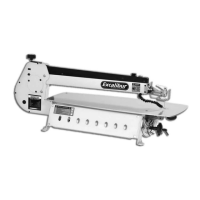
NOTE: Make sure the both rip fence rails are parallel to the fair left of the left extension table (26),
(See fig 52)
Replace the rip fence assembly (20) on the saw bench (1), as described on page 15.
951537 10" and 191541 12" Table Extension Kits (Box 2 of 2)
The left extension table, with both fence
rails parallel to the edge.
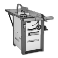
Table Extension Kit, (Setup 1) assembled
Fig 52
Fig 53
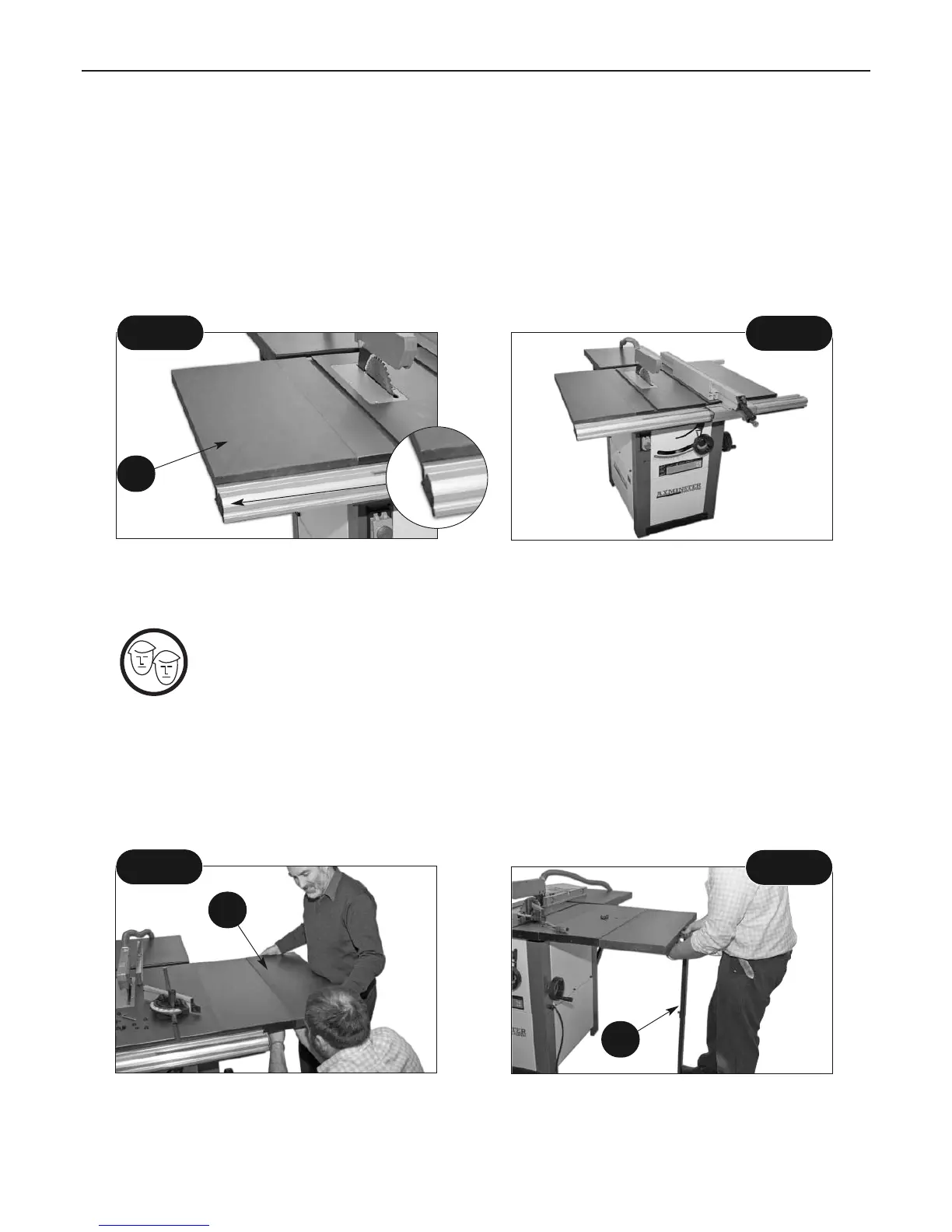
Setup 2
Fig 54
Fig 55
26
The Left extension table (26) can be repositioned to the end of the right extension
table to create a large surface area, in doing so it also freeʼs up the space to
attach the sliding table assembly (order no: 951539).
First remove the rip fence assembly (20) and place safely aside, loosen both rip fence rails
(33-34) and slide them to the right. Undo the four M8 x 30mm hex bolts and remove the left
table. Attach the left table to the right table using the four M8 x 30mm bolts,washers and
nuts as before, (WARNING: YOU MUST ENSURE THAT THE NUTS IS FULLY ENGAGED ON THE
BOLTS BY SERVERAL TURNS, BEFORE RELAXING THE LIFTING EFFORT). Tighten all the bolts
securely. (See fig 54)
Locate the table support leg (27), the threaded rubber foot (28) and two M8 x 20mm hex bolts,
washers and nuts (31). Line up the two middle holes to outside edge of the table with the
pre-drilled holes in the support leg bracket (27) and fasten securely using the M8 bolts, washers
and nuts. (See figs 55-56)
26
27