Initial Assembly
11
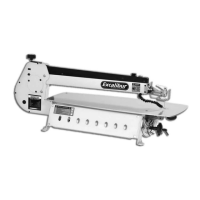
Fig 11
Fig 12
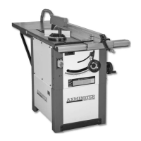
Fig 13
Fig 14
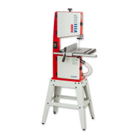
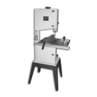
When everything is tightened up, the machine can now be tipped over, towards its blind face until
it is resting on the pallet with its legs on the floor. Lift the machine upright. (See figs 13-14)
Blind face
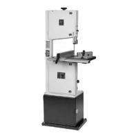
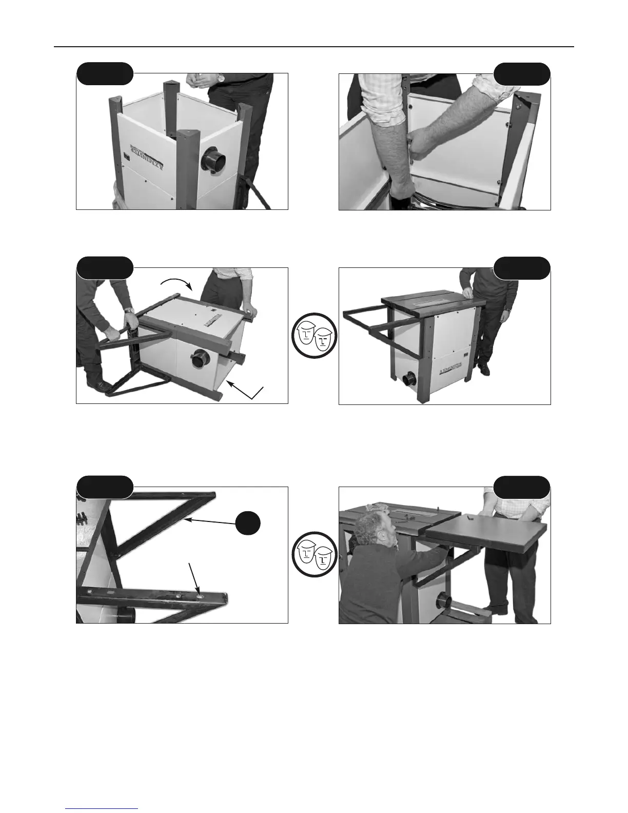
Locate the table and the other 4 No. M8 caphead bolts and washers (9A). Mount the table onto
the brackets, Note: that the securing bolts need to feed through the elongated holes in the
bracket (7). (the extension table is spaced off the main table to allow clearance for the rear
clamping rail and the rip fence). Leave all bolts finger tight at this time.
Fig 15
Fig 16
Elongated holes
7
Locate the two hand wheels (10). Fit the hand wheels onto the shafts for the tilt mechanism drive
and the rise and fall mechanism. (See figs 17-18-19-20)
Note: the square key slots on the shafts, align the holding grubscrews with these slots.
Tighten securely. Check their security by raising and lowering and tilting the saw blade.
NOTE. Please ensure that the rise and fall LOCK is loosened before operating the mechanism.
Fitting Hand Wheels
Continues Over....
 Loading...