Initial Assembly
16
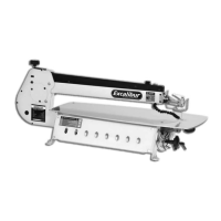
Locate the Rip Fence Extension (21), the two M6 x 70mm ‘T’ bolts and M6 knobs (24A). Slot the
two ‘T’ bolts into the fence extension recess, see figs 41 and 42. Slot the bolts into the pre-drilled
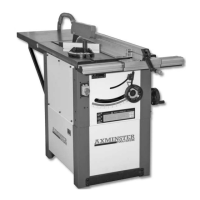
holes in the fence extension and secure in place with the M6 knobs. (See figs 43-44)
Fig 41 Fig 42
Fig 43
Fig 44
Fig 45
NOTE: The rip fence extension (21) can be repositioned to the opposite direction for guiding thin
timber pieces through. (See fig 45)
21
24A
M6 Knob
951537 10" and 951540 12" Saw Bench (Box 1 of 2)
Mitre Fence Assembly
Rip Fence Extention Assembly
Fig 46
Fig 47
11
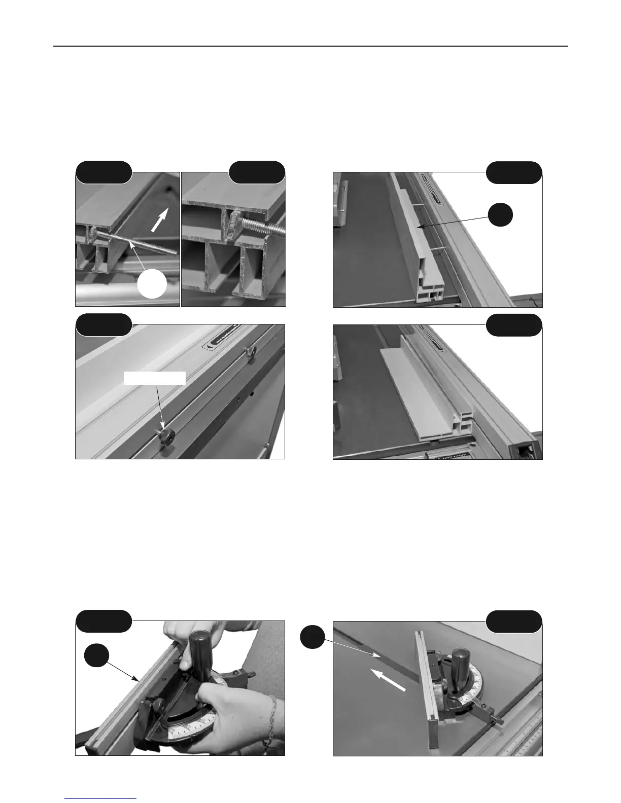
Locate the Mitre Fence and Extension (11), loosen the clamping screw knobs on the extension
and slot each into the slot recesses on the mitre fence, tighten to clamp the extension in place.
(See fig 46) Introduce the nose of the bar (12) into the required ‘T’ slot in the main table. (See fig
47)
Note: With the rear extension table fitted it is not possible to push the small mitre fence
completely through. However, the travel is such that the fence is able to travel well past the
cutting edge of the saw.
12