Initial Assembly
20
951539 10" and 12" Sliding Table Kits (Box 1 of 2) and (Box 2 of 2)
Locate and identify the mounting brackets (36) and the height adjustor blocks (52) (in Box 2 of2).
These are mounted on the outside faces of the upper chassis legs. They are anchored against
clamping plates (37) that are behind the face of the legs.
NOTE: These clamping plates are 'loose items', each is initially held in place by three M10 x 19mm
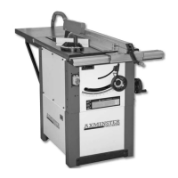
hex bolts (40A). Unscrew the caphead bolt in the height adjustor block (52), see fig 64, until the
recessed hole for the caphead bolt (40A) is clear, fit it through the height adjustor block and screw
it back into its position. Screw it almost home. Next fit a caphead bolt through the top hole of the
bracket (36), and with the bracket tilted to one side, screw it back into its position. (See figs 62-63
and 65)
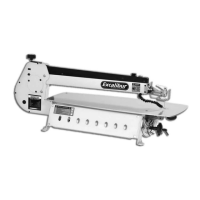
Line up the holes in the clamping plate in
ready ness for fitting mounting bracket
Mounting plate in position
Fig 62
Fig 63
Unscrew the caphead bolt until the
recessed hole is clear
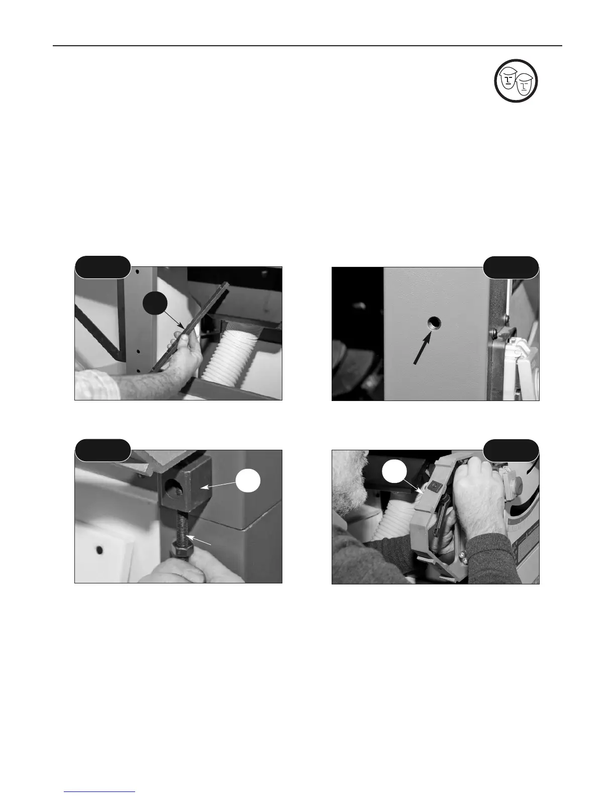
Attaching the mounting bracket (36) to the
side of the saw bench (1)
Fig 64
Fig 65
37
52
36
Caphead bolt
Fit a bolt (40A) through the bottom hole of the bracket, screw it back into its position. Align the
adjustor block (52) as near vertical as you can judge and fasten the caphead bolt. Screw the
adjusting caphead bolt back through the block until it touches the lower face of the mounting
bracket (36). (See fig 66) Nip the securing bolts for the mounting bracket. Fit the other bracket in
the same way. NOTE: When screwing the adjusting bolt back through the block, set it to leave the
brackets at approximately the same height. (See fig 67)
Unscrew the slide rail assembly lift and shift handles (A) so that the square clamps have plenty of
movement.
Mounting Bracket/Adjuster Block Assembly
 Loading...