Initial Assembly
19
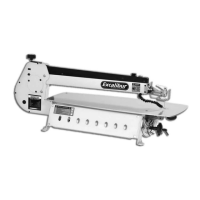
Fig 56
Fig 57
27
Screw the threaded rubber foot (28) on to the end of the support leg (27), until it’s tight. (See fig
57) Unlock the caphead clamping bolt of the support leg and allow the inner section to slide
through until the foot is resting on the floor. DO NOT put the leg under tension at this time.
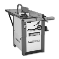
'Nip' up the clamp bolt (See fig 58)
28
Support leg caphead clamping bolt
Replacing both rip fence rails (33-34)
Fig 58
Fig 59
27
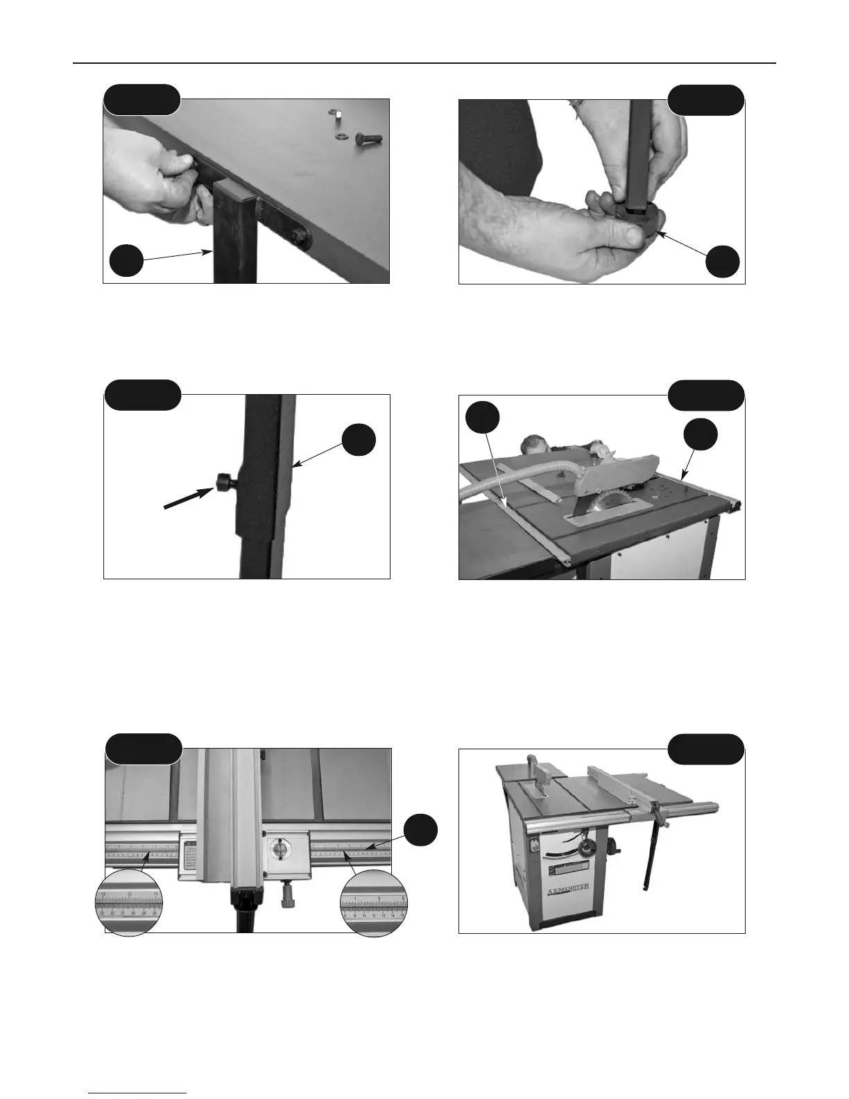
Replace both long rip fence rails (33-34) as described on the previous page and replace the rip
fence assembly (20) on the saw bench (1), as described on pages 15 and 18.
The Measuring Scale extension label (35) can be used for the different setup configurations. (See
fig 60)
Measuring Scale Extension label
Table Extension Kit, (Setup 2) assembled
Fig 60
Fig 61
34
33
35
 Loading...