Initial Assembly
23
Lower the fence mounting (51B) onto the rear quadrant NOTE: position the fence so the
sacrificial plastic orange tongue is against the table to the right of the mounting. Position the
fence so when it is pivoted it will not encroach into the saw slot. Lightly tighten the two caphead
bolts on the fence mounting (51B). Replace the clamping handle and washer you removed earlier.
(See fig 77)
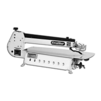
Screw the post into the tapped hole in the
sliding table (39)
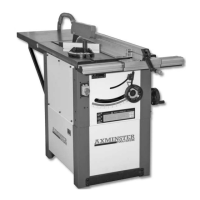
Fitting the workpiece hold down clamp
onto the main tool post
Fig 78
Fig 79
Introduce the Tool Post (38) through the table fence mounting (51B) and screw the post into the
tapped hole in the sliding table (39) (See fig 78). The post is shouldered so it holds the Fence
Mounting in position against the table. Fit the workpiece hold down clamp onto the main tool
post and pinch up the clamping knob, see fig 79 and tighten the caphead bolts on the table fence
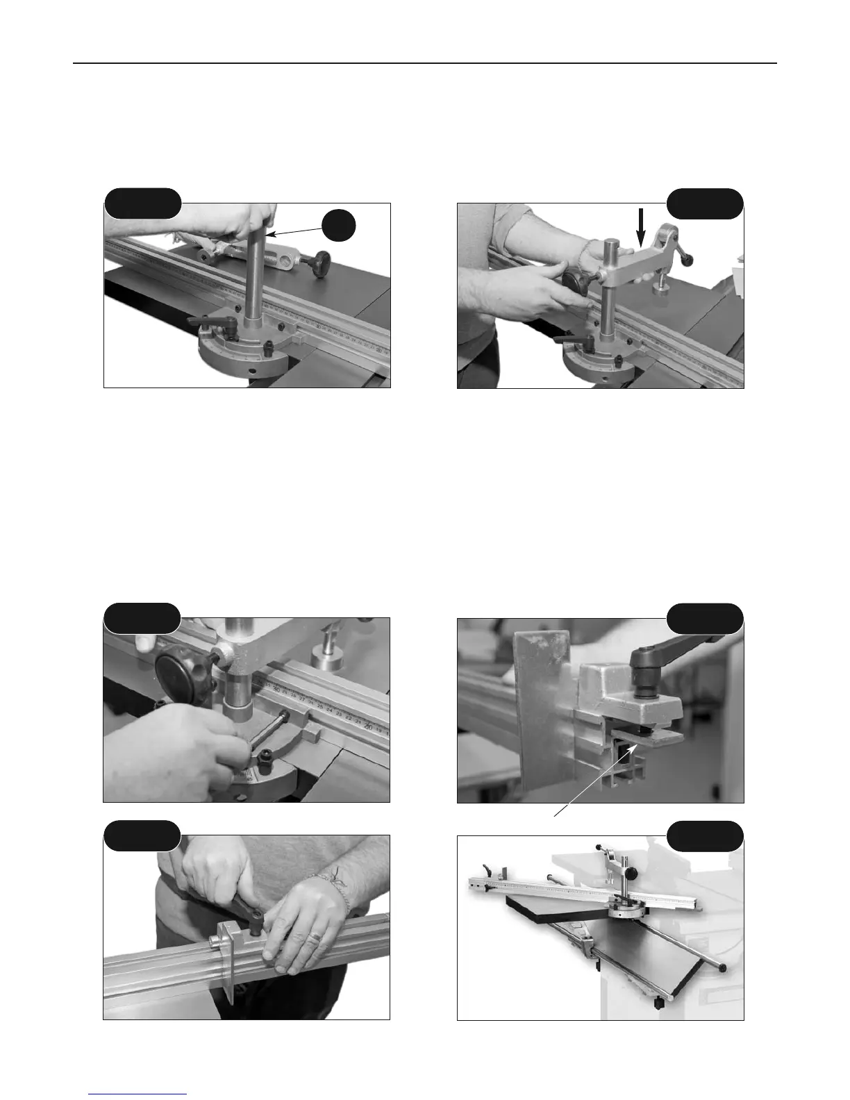
mounting casting. (51B) (See fig 80) Mount the distance stop (53) by introducing the square
clamp into the wide channel in the top of the fence extrusion and clamp it in position using the
lever handle. (See fig 81-82) Sliding table assembled. (See fig 83)
Fig 81
Fig 82
Fig 83
38
Fig 80
Square clamp
 Loading...