6. Use conduit holes where cables enter the enclosure from the bottom. Use suitably certied plugs to seal any holes that are
not used for cable entry. A cable gland kit is included for inserting the transducer and power cables.
1/2 in. NPT,
1/2 in. BSPP, or
M20 Threads
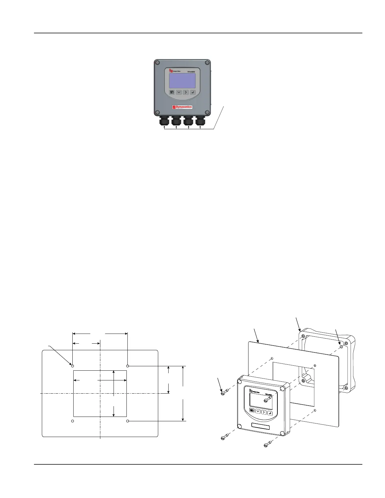
Figure 20: Conduit holes
OTE:N Use suitably certied fittings/plugs to maintain the watertight integrity of the enclosure. Generally, the right conduit
hole (viewed from front) is used for power, the left conduit hole for transducer connections, and the center holes are
used for I/O wiring.
7. Install the wires through the gland nuts and connect the wires to the removable terminal blocks. See “Wiring the
Transmitter” on page14.
8. Set up the meter. See “Initial Meter Setup” on page21 for instructions.
9. Install the adjustable transducers according to instructions in the transducer user manual.
10. Wire the transducers to the transmitter.
11. Plug the wired terminal blocks into the main board.
12. Reassemble the cover. Torque the cover screws to 45 in-lb.
Installing a Panel-Mount Meter
1. Measure and cut a mounting hole into the customer-supplied panel to the dimensions shown in Figure 21.
2. Remove the 4 screws and 4 O-rings holding the front of the unit to the frame.
3. Verify that the gasket is secure in the mounting bezel.
4. Guide the front of the unit through the panel cutout.
5. Insert the 4 screws through the front of the unit and the panel.
6. Apply one O-ring to each screw from the back of the panel.
7. Align the front of the unit to the frame.
8. Tighten the 4 screws and torque them to 45 in-lb.
Ø 0.252 in. thru
typ.
4.80 in.
(121.92 mm)
5.50 in.
(139.70 mm)
5.70 in.
(144.78 mm)
5.70 in.
(144.78 mm)
2.85 in.
(72.93 mm)
2.85 in.
(72.39 mm)
Customer-supplied panel
Screws (×4)
O-rings (×4)
Frame
Figure 21: Panel cutout dimensions and installation exploded view
Installation
Page 13 October 2019 TTM-UM-02222-EN-04

 Loading...