Mains Power
IMPORTANT: The measuring device does not have an internal circuit breaker. For compliance with IEC 61010-1, a switch in close
proximity to the transmitter is required so that the power supply line can be easily disconnected from the mains.
The transmitter may be operated from 90…250V AC, 47…63 Hz, 24VA maximum power source.
OTE:N Mains AC-powered transmitters are protected with 1A, 250V AC, 5×20 mm, slow-blow, field-replaceable fuse.
WARNING
TO PREVENT SHORTING OUT THE MAINS AC POWER, YOU MUST REPLACE THE TERMINAL BLOCK COVER ON THE AC
MODULE AFTER WIRING THE POWER.
Remove the terminal block covers before wiring and replace them after wiring:
1. Grasp the sides of the cover and gently pull it up.
2. Insert wires into the slots on the cover and screw them down to secure.
3. Align the cover in its original orientation over the terminal block and push down to connect.
TB400 External 85…264V
85 . . . 264V AC
Return
Chassis Ground
24V DC
0V DC
.
1
2
TB100
AC-L
3
AC-N
AC-DC Power Module
(24VA max.)
Protective
Ground
Red
Black
Green
Factory Wired
(Main power wiring must be of material
VW-1 or better.)
(Acceptable wire sizes: 18…12 AWG)
+
-
Switch
or
Circuit
Breaker
Connect protective earth conductor to terminal 3.
Figure 27: AC/DC power connections
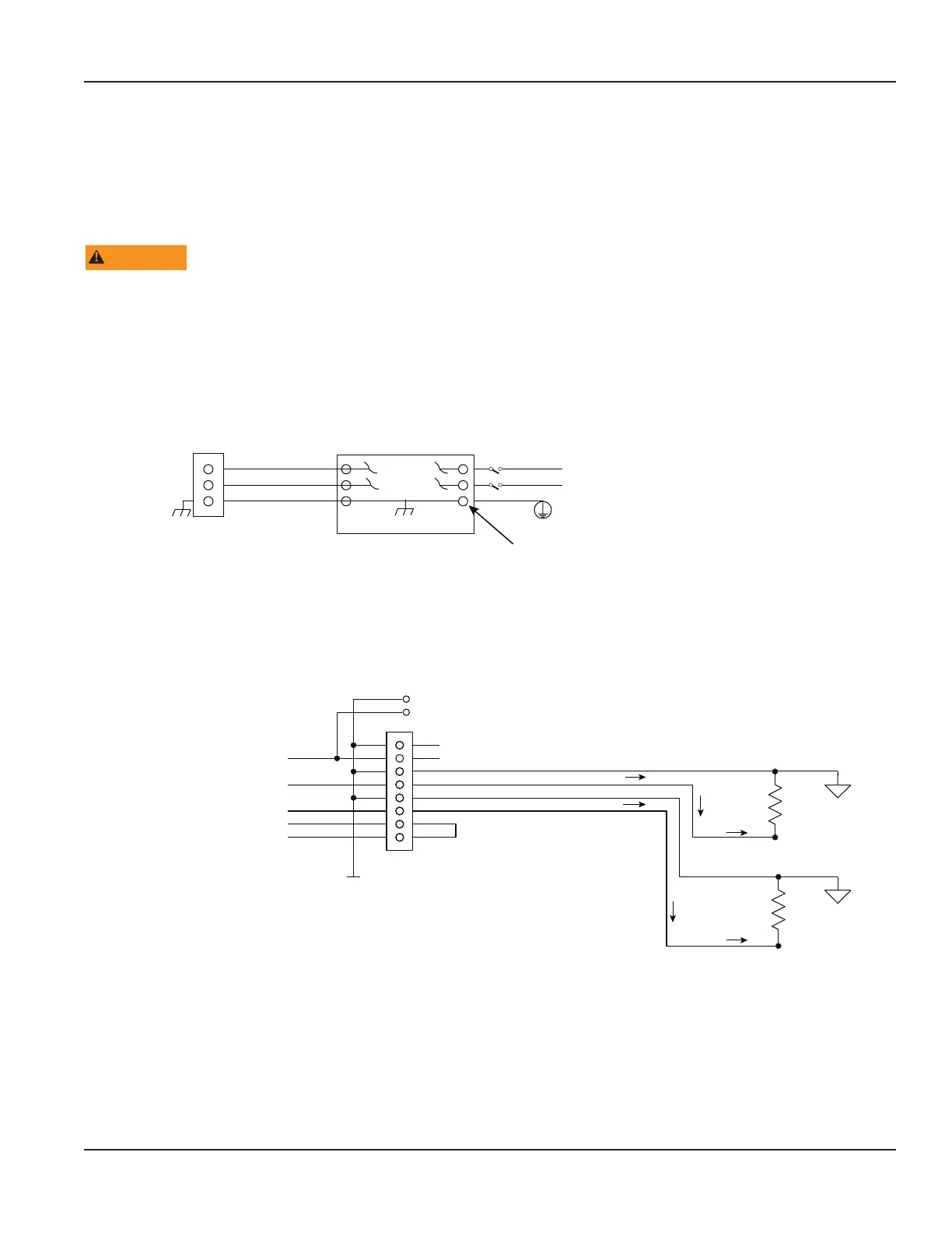
4…20 mA Output Wiring
The 4…20 mA output transmits an analog current signal that is proportional to system flow rate. The 4…20 mA output can be
internally or externally powered and can span negative to positive flow rates.
Both current loops are ISOLATED from DC GND or Power.
TB600
External Equipment
4…20 OUT 1 Current #1 Output
4…20 OUT 2 Current #2 Output
800 Ohms max.
800 Ohms max.
ISO_GND
Black
Red
TP605
TP604
(Acceptable wire sizes: 28…12 AWG)
TYP 24V DC
1
2
3
4
5
6
7
8
NOTE: 4…20 OUT 2 available
with Energy model only.
Figure 28: Typical 4 . . . 20 mA interface using internal isolated 24V DC source
Wiring the Transmitter
Page 17 October 2019 TTM-UM-02222-EN-04

 Loading...