Rated Conditions of Terminals
• Mains AC 85…264V AC
Wire 18-12AWG UL AWM 1007 Type 1007
• 9…28V DC, 20…26VAC
Wire 20AWG UL AWM 1007 Type 1007
• Transducer Cables
Badger Meter supplied cable
• Digital Outputs/Inputs, Current Output, RS-485, RTD or Encoder Interface
• Wire 28…12 AWG UL AWM 1007 Type 1007
Wiring the Transducer
OTE:N Submersible transducer cables are larger diameter. Each cable requires a separate conduit hole. The standard yellow
cable and high temperature cables are small enough to use a single cable gland with a 2-hole grommet.
OTE:N Transducer cables have two wire-color combinations. For the blue and white combination, the blue wire is positive
(+) and the white wire is negative (–). For the red and black combination, the red wire is positive (+) and the black
wire is negative (–). The transducer wires are labeled to indicate which pair is upstream or downstream.
1. Guide the transducer terminations through a conduit hole in the bottom of the enclosure.
2. Secure the transducer cable with the supplied conduit nut (if exible conduit was ordered with the transducer).
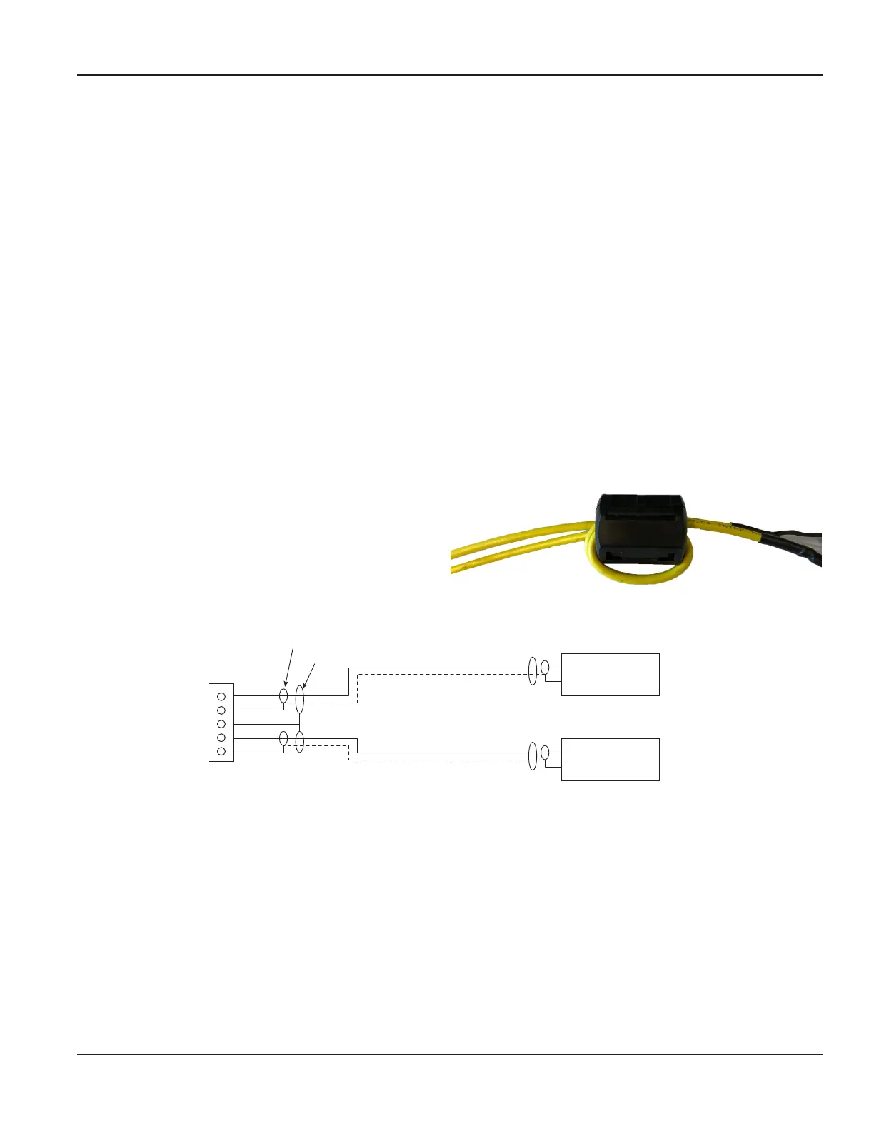
3. Install the ferrite to the cable:
a. To open the ferrite, pull the fastener away from the
body of the ferrite.
b. Wrap the cable tightly around half of the ferrite and
place the cable into the groove.
c. Snap the ferrite shut.
4. The terminals within the transmitter are screw-down barrier terminals. Connect the wires at the corresponding screw
terminals in the transmitter. Observe upstream and downstream orientation and wire polarity. See Figure 24.
TB300
Red
Black
Green (2)
Red
Black
Inner Shield
Outer Shield
69039, Triax Cable
Upstream+
Upstream-
Downstream+
Downstream-
Transducer
Figure 24: Upstream/downstream transducer
Wiring the Transmitter
Page 15 October 2019 TTM-UM-02222-EN-04

 Loading...