Power
Connect power to the screw terminal block in the transmitter.
• Low voltage power can use any available conduit hole in the enclosure.
• Line voltage AC power must use the right conduit hole, which is aligned with the terminal block on the AC power board.
• Use wiring practices that conform to local and national codes such as The National Electrical Code Handbook in the U.S.
ANY OTHER WIRING METHOD MAY BE UNSAFE OR CAUSE IMPROPER OPERATION OF THE TRANSMITTER.
OTE:N This transmitter requires clean electrical line power. Do not operate this transmitter on circuits with noisy
components (such as fluorescent lights, relays, compressors, or variable frequency drives). Do not use step-down
transformers from high voltage, high amperage sources. Do not to run signal wires with line power within the same
wiring tray or conduit.
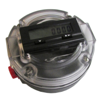
9…28V DC Power
The transmitter may be operated from a 9…28V DC source, as long as the source supplies a maximum of 8 Watts of power.
Connect the DC power to 9…28V DC In, power return, and chassis ground, as in Figure 25.
OTE:N DC-powered transmitters are protected from major catastrophe with an internal 2.0 Amp slow-blow fuse. If this fuse
is blown, replace the transmitter or return it to the factory for repair.
IMPORTANT: A Class II DC power supply is required.
+
-
TB400
External Equipment
Power Supply (9 . . . 28V DC)
Power Supply (Return)
Chassis Ground
(Acceptable wire sizes: 28…12 AWG)
Switch
or
Circuit
Breaker
Figure 25: Power supply 9…28V DC
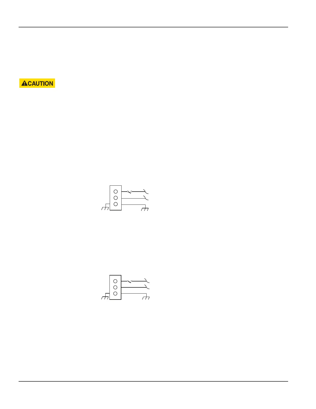
20…26V AC Power
The transmitter may be operated from a 20…26V AC source, as long as the source supplies a maximum of 8 Watts of power.
Connect the AC power to 20…26V AC In, power return, and chassis ground, as in Figure 26.
OTE:N 24V AC powered transmitters are protected from major catastrophe with an internal 2.0 Amp slow-blow fuse. If this
fuse is blown, replace the transmitter or return it to the factory for repair.
TB400 External Equipment
Power Supply (20 . . . 26V AC)
Power Supply (Return)
Chassis Ground
(Acceptable wire sizes: 28…12 AWG)
+
-
Switch
or
Circuit
Breaker
Figure 26: Power supply 20…28V AC
Wiring the Transmitter
Page 16 October 2019TTM-UM-02222-EN-04

 Loading...