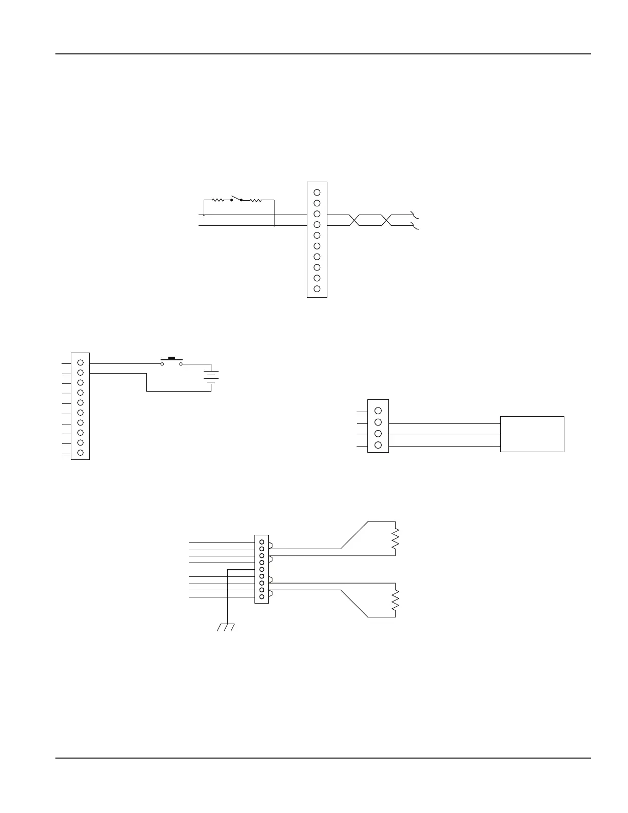
RS485 Output
The RS485 feature allows up to 126 transmitters to be placed on a single three-wire cable up to 4000 feet. All transmitters are
assigned a unique numeric address that allows all of the transmitters on the cable network to be independently accessed.
Either Modbus RTU or BACnet MS/TP protocol is used to interrogate the transmitters.
Flow rate and total can be monitored over the digital communications bus.
When a USB programming cable is connected, the RS485 and frequency outputs are disabled.
TB700
External Equipment
3
4
RS485 +
RS485 −
A B
60.4 Ohms
60.4 Ohms
Terminator Resistors
(Enabled through Parameter Setting)
Figure 32: Typical RS485 interface
Digital Input Wiring AquaCUE/BEACON Endpoint Wiring
TB700
1
2
3
4
5
Reset Total +
Reset Total -
Push-button
5…30V DC
6
7
8
9
10
TB500
1
2
3
4
AquaCUE/BEACON
Endpoint
DGND (Black Wire)
Endpoint VccClk In (Red Wire)
Endpoint Data Pulse Out (Green Wire)
NOTE: Non-isolated
(Acceptable wire sizes: 28…12 AWG)
Figure 33: Digital input—reset totalizer Figure 34: AquaCUE/BEACON wiring
RTD Interface Wiring (Energy Models Only)
External Equipment
Chassis_GND
TB900
PT100 or PT1000 RTDs
Temp #1
Temp #2
1
2
3
4
5
6
7
8
9
RTD1 Ex +
(Acceptable wire sizes: 28…12 AWG)
RTD1 Sense +
RTD1 Sense -
RTD1 Ex -
RTD2 Ex +
RTD2 Sense +
RTD2 Sense -
RTD2 Ex -
Figure 35: Two-wire RTD interface
Wiring the Transmitter
Page 19 October 2019 TTM-UM-02222-EN-04

 Loading...