REPLACEMENT PROCEDURES
WARNING
DISCONNECT POWER BEFORE OPENING THE ENCLOSURE.
Tools Required
• A Phillips #2 screwdriver
• A flat blade screwdriver
• Tweezers for electronics
• A workbench that prevents ESD damage to the electronics
CONTAINS PARTS AND ASSEMBLIES SUSCEPTIBLE TO DAMAGE BY ELECTROSTATIC DISCHARGE ESD. BEFORE PICKING
UP AN ESDSENSITIVE ELECTRONIC COMPONENT, DISCHARGE YOURSELF BY TOUCHING A GROUNDED BARE METAL
SURFACE OR APPROVED ANTISTATIC MAT.
OBSERVE PRECAUTIONS FOR HANDLING ELECTROSTATIC-SENSITIVE DEVICES.
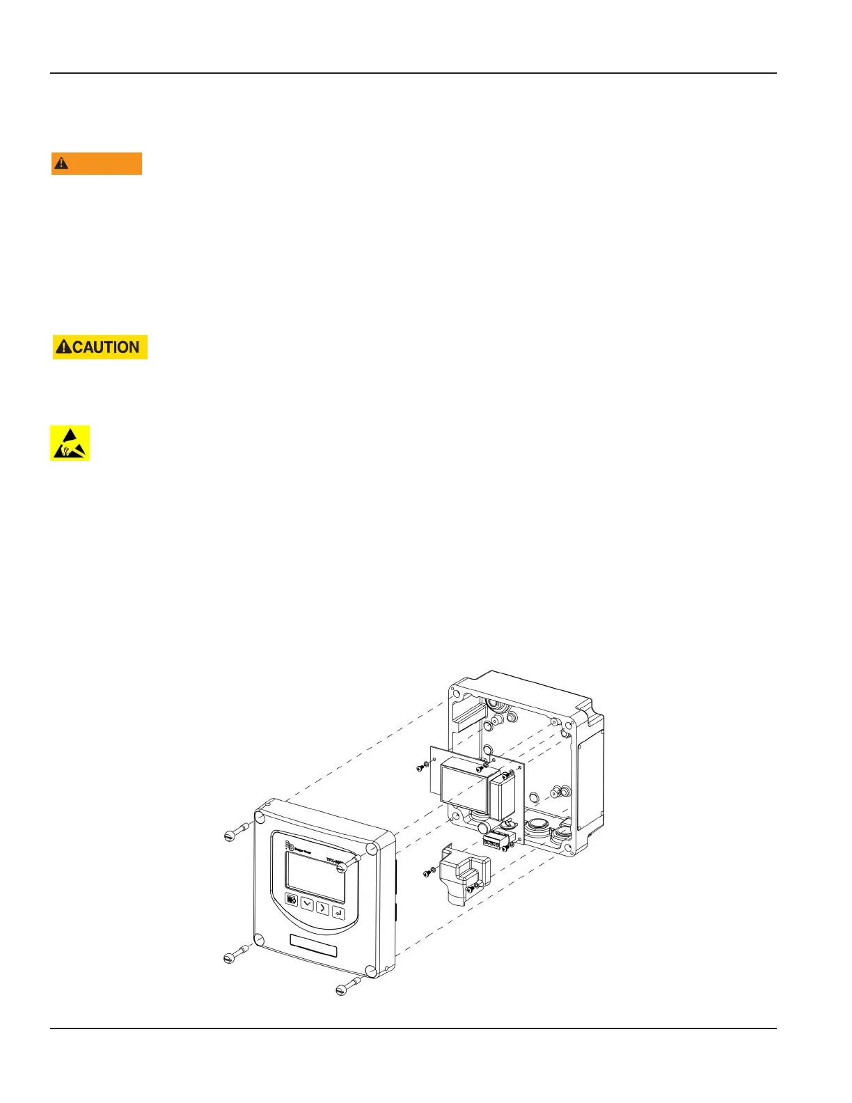
Replacing an AC Module
1. Turn o the power.
2. Open the enclosure.
3. Unplug the DC power wire connector from the terminal block on the main board.
4. Remove (2) M3 pan head phillips screws that secure the cover over the AC power terminal block.
5. Unplug the wire connector from the terminal block on the AC module.
6. Remove the remaining (4) M3 pan head phillips screws and lock washers that secure the AC module to the enclosure base.
7. Remove the AC module.
Installation is in the reverse order.
Figure 41: Replacing an AC module
Replacement Procedures
Page 48 October 2019TTM-UM-02222-EN-04

 Loading...