INTRODUCTION
FEATURES
1 - 2 I-E96-207A
®
The controller module has two connection points for external
signals and power (P1 and P3). P1 connects to logic power that
drives the module circuits (refer to the troubleshooting sec-
tion). Digital and analog signals are input and output through
connector P3 using a cable connected to a TU/TM (refer to the
troubleshooting section). The terminal blocks (physical con-
nection points) for field wiring are on the TU/TM.
FEATURES
The modular design of the COM, as with all INFI 90 modules,
allows for flexibility when you are creating a process manage-
ment strategy. It brings analog and digital signals into the sys-
tem and outputs analog and digital signals to the process.
The COM accepts digital signals of 24 VDC to 125 VDC. Indi-
vidual voltage and response time jumpers on the module con-
figure each input. It accepts analog signals of 1 to 5 VDC, 4-20
mA (single ended or differential). The analog output mode is
selectable. A dipswitch selects current or voltage mode for each
analog output depending on the process requirements. It out-
puts 4 to 20 mA or 1 to 5 VDC analog signals and 24 VDC digi-
tal signals.
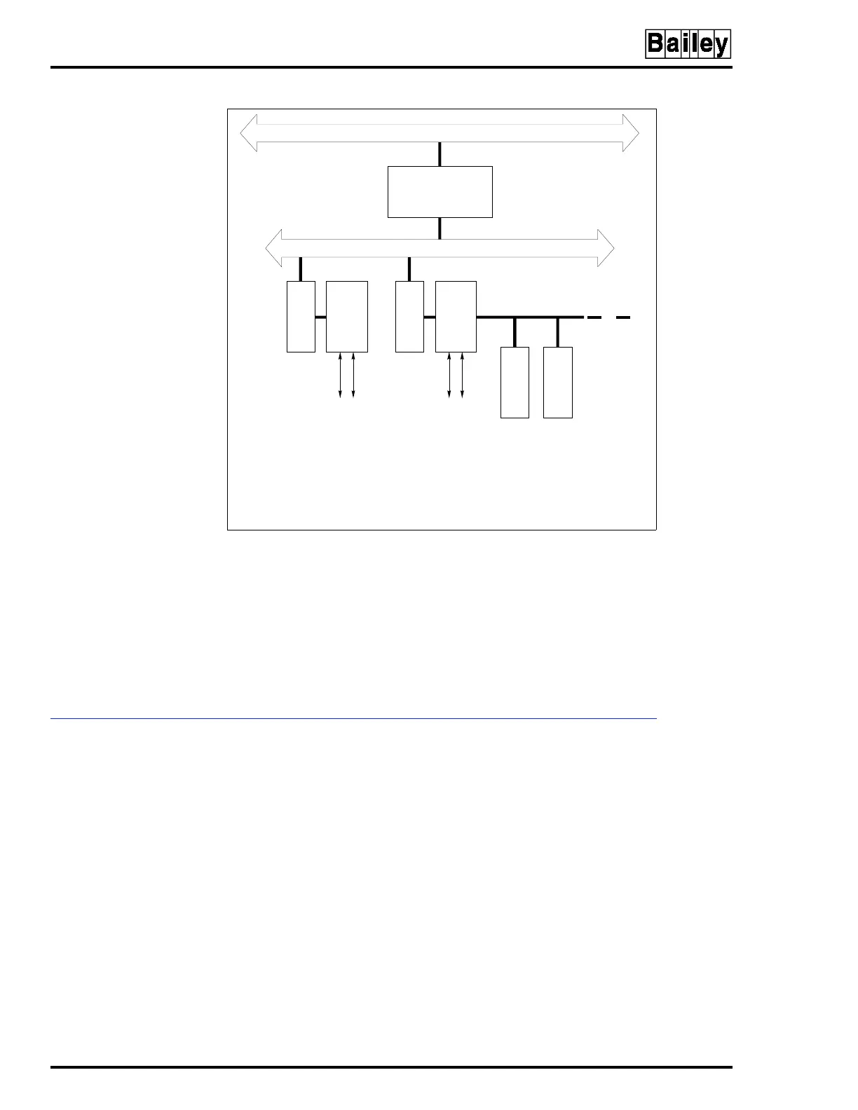
Figure 1-1. INFI 90 Communication Levels
COMMUNICATION HIGHWAY (INFI-NET OR PLANT LOOP)
MODULE BUS
COM COM
SAC SAC
TCS TCS
ANALOG AND
DIGITAL I/O
FIELD WIRING
ANALOG AND
DIGITAL I/O
FIELD WIRING
COMMUNICATION
MODULES
T00139A
LEGEND:
COM = CONTROLLER MODULE
MFC = MULTI-FUNCTION CONTROLLER
SAC = CONTROL STATION
SLAVE = SLAVE MODULE
TCS = CONTROLLER TERMINATION UNIT
TU = TERMINATION UNIT