TROUBLESHOOTING
MODULE PIN CONNECTIONS
I-E96-207A 6 - 3
MODULE PIN CONNECTIONS
The controller module has two connection points for external
signals and power (P1 and P3). Table 6-4 shows the module pin
connections.
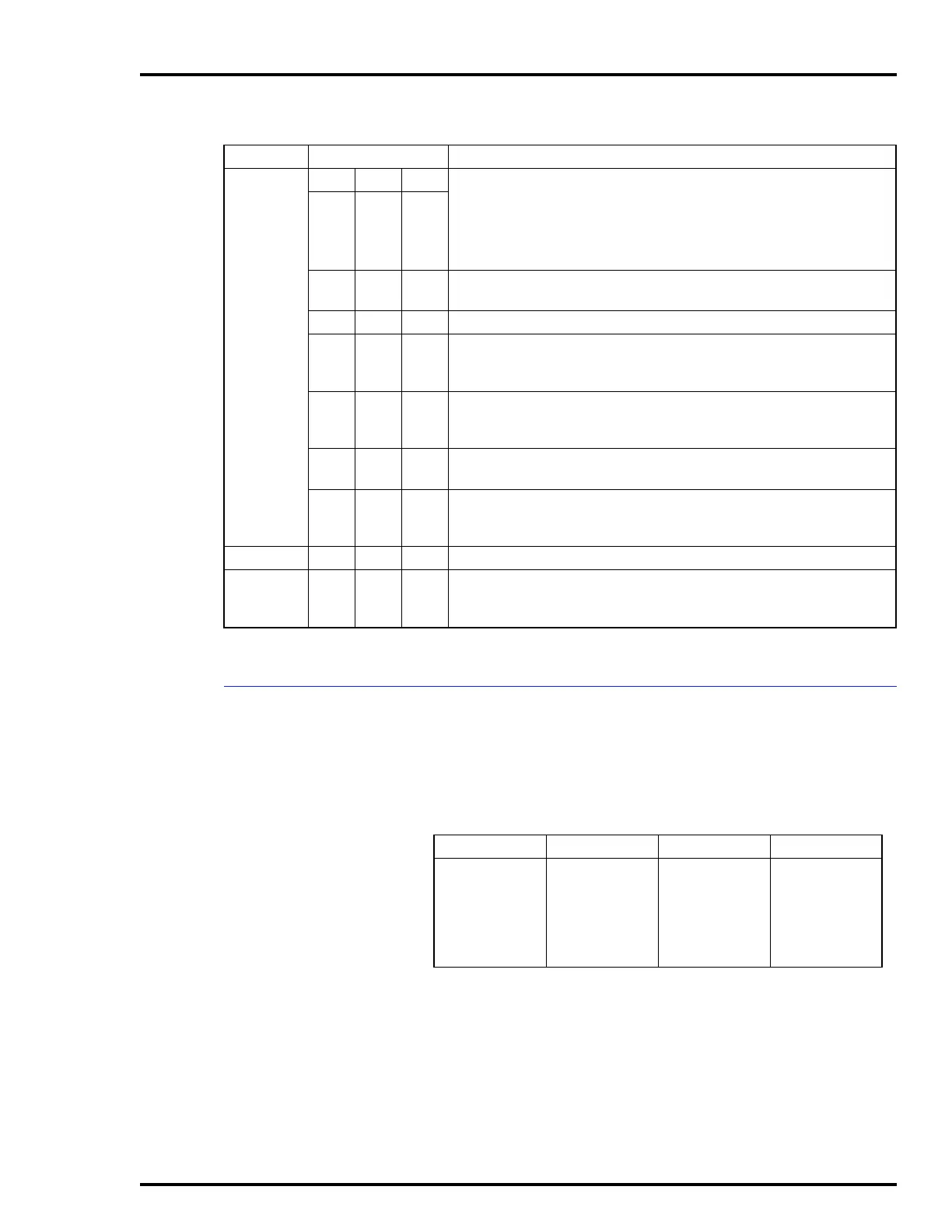
Bytes
345
NVRAM Error: Write Failure
Checksum Failure
Bad Data
Reset During Write
01 01
02
03
FF
—
—
—
—
02 00 04
05
Analog Input Reference Error: 1 Volt Ref.
Analog Input Reference Error: 5 Volt Ref.
03 00 —
Missing I/O Expander Board
05 (1) (2
) Configuration Error - Undefined Block
(1) = Block making reference
(2) = Block being referenced
06 (1) (2)
Configuration Error - input data type is incorrect
(1) = Block number making reference
(2) = Block number being referenced
08 (1) —
Trip block activated
(1) = Block number of Trip block
09 (1) (2)
Function Not Allowed in Segment
(1) = Segment block number
(2) = Block number in error
0A — —
Too Many Segment Control Blocks
0B (1) (2)
Segment Control Block Priority Violation
(1) = Block number of first segment
(2) = Block number of segment in error
NOTE:
All block numbers are encoded in BCD (binary coded decimal) with (1) = MSB (most significant byte) and
(2) = LSB (least significant byte).
Example:
Block Number 1024 — (1) = 10, (2) = 24.
Table 6-3. Status Byte Descriptions
Field Value Description
Table 6-4. P1 Power Pin Connections (COM03/04)
Pin (P1) Connection Pin (P1) Connection
1
2
3
4
5
6
+5 VDC
+5 VDC
NC
NC
Common
Common
7
8
9
10
11
12
+15 VDC
-15 VDC
PFI
PFI
NC
NC
NOTES:
NC = Not Connected
PFI = Power Fail Interrupt