DESCRIPTION AND OPERATION
PROCESS INPUT/OUTPUT INTERFACING
I-E96-207A 2 - 9
PROCESS INPUT/OUTPUT INTERFACING
The maximum input/output capability of the controller mod-
ule from the field (via the termination unit) is four analog
inputs, two analog outputs, three digital inputs and four digital
outputs. Additional input/output capabilities are provided by
the module bus or the communication highway.
Field inputs correspond to terminals on the terminal blocks of
the TCS and are conditioned by the user configured dipshunts.
The cable (NKTU01), attached to connector P1 of the TCS, car-
ries these inputs to the controller (via card edge P3). The con-
troller modules analog-to-digital (A/D) converter converts field
analog signals to digital levels for processing. Digital-to-analog
(D/A) conversion circuits convert digital values to analog sig-
nals via analog output 1 or analog output 2. The controller
configuration dictates how the controller module will process
this data.
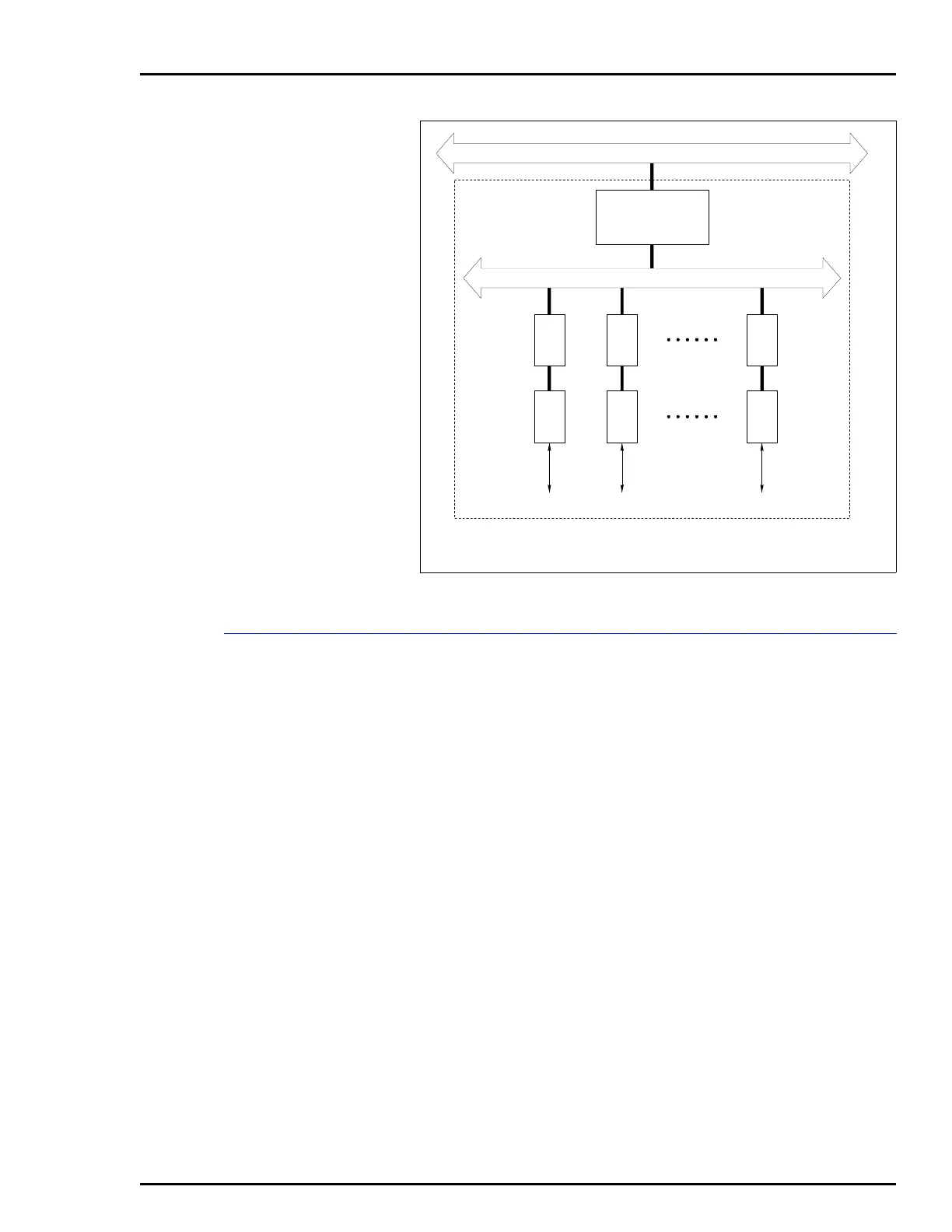
Figure 2-4. Communication Highway/Module Bus Relationship
COMMUNICATION HIGHWAY (INFI-NET OR PLANT LOOP)
MODULE BUS (32 MODULES MAX)
COM COM COM
TU TU TU
I/O I/O I/O
COMMUNICATION
MODULES
T00112A
LEGEND:
COM = CONTROLLER MODULE
TU = TERMINATION UNIT
PROCESS
CONTROL UNIT