INTRODUCTION
I-E96-207A 5 - 1
SECTION 5 - OPERATING PROCEDURES
INTRODUCTION
This section explains the front panel indicator and start-up
procedures for the Controller Module (IMCOM03/04).
MODULE STATUS INDICATOR
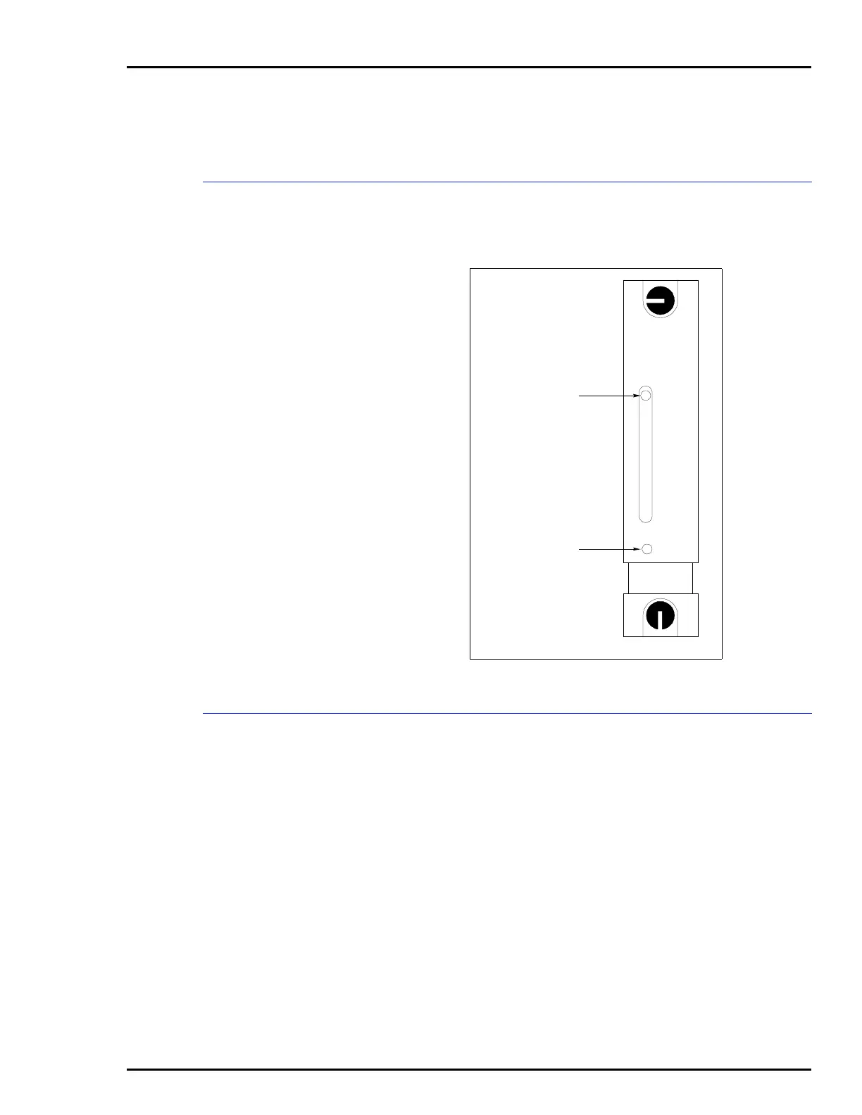
The controller module has a front panel module status LED
indicator to aid in system test and diagnosis. The location of
the indicator is shown in Figure 5-1. Table 5-1 explains the
three states of the status LED indicator (refer to the trouble-
shooting section to determine corrective actions).
Figure 5-1. IMCOM03/03 Front Panel
STATUS LED
RESET SWITCH
T00119A
IMCOM03