TERMINATION UNIT CONFIGURATION (NTCS02)
INTRODUCTION
I-E96-207A A - 5
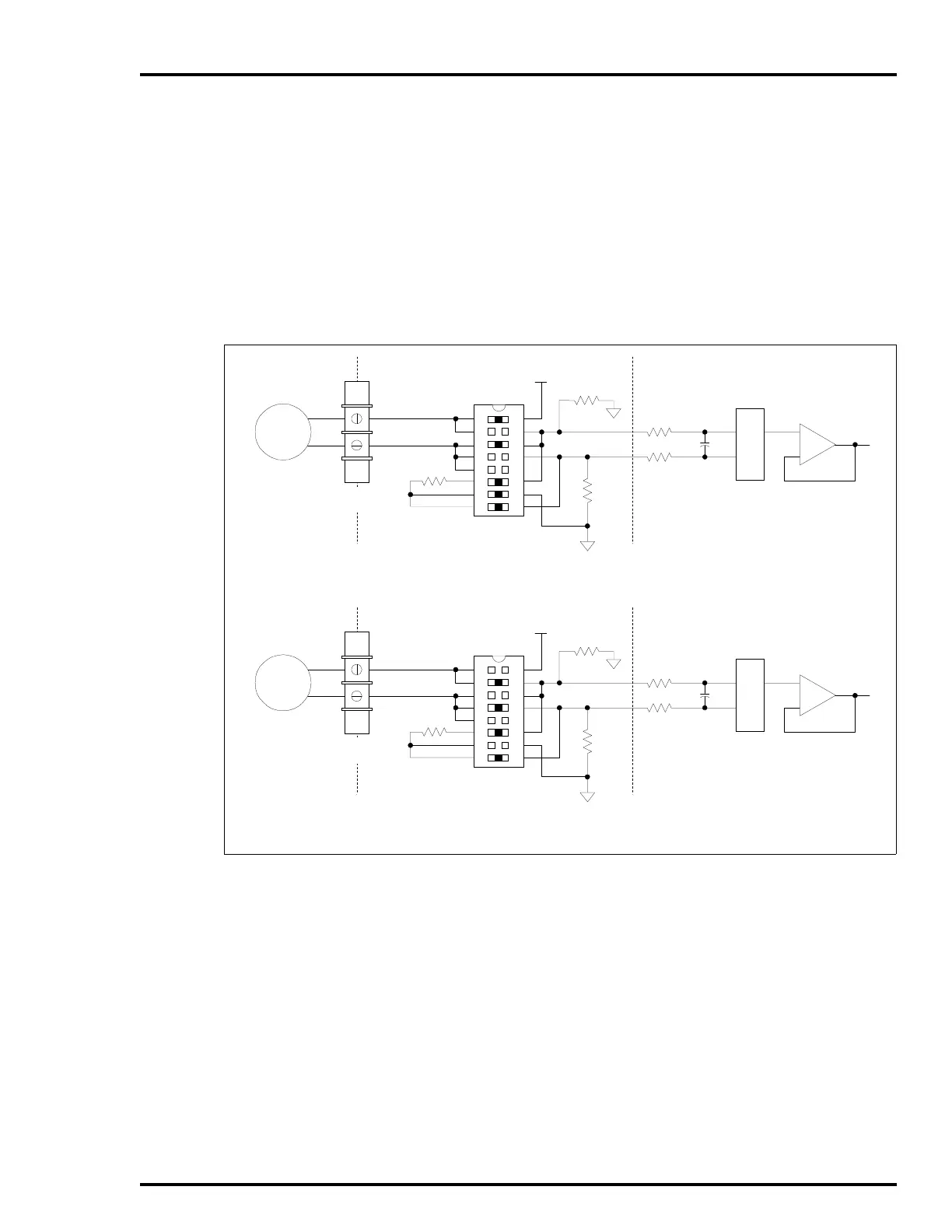
Table A-1 lists the TCS analog output dipshunts. Figures A-3,
A-4, A-5 and A-6 show the TCS dipshunts, and the I/O signal
path from the field device to the controller module for a termi-
nation unit application. Refer to Table A-1 to determine the
dipshunt strapping to configure your application. Figure A-2
shows the terminal assignments for the digital and analog I/O
signals. Refer to this figure when connecting field wiring to the
TCS.
Figure A-7 and Figure A-8 show COM to TCS cable
connections.
Figure A-3. Analog Input Dipshunt Configurations
T00122A
+24 V
(I/O POWER)
FIELD
XMTTR
DIPSHUNTS XU1-XU4 CONTROLLER INPUT CIRCUITRY
161
152
143
134
125
11
6
107
98
POWERED 4-20 mA INPUT
+
–
TERMINAL
BLOCK
–
+
MUX
+24 V
(I/O POWER)
FIELD
XMTTR
DIPSHUNTS XU1-XU4 CONTROLLER INPUT CIRCUITRY
161
152
143
134
125
11
6
107
98
UNPOWERED 4-20 mA INPUT
+
–
TERMINAL
BLOCK
–
+
MUX