INSTALLATION
SETUP
3 - 6 I-E96-207A
®
ANALOG OUTPUTS (S2 AND S3)
Analog output number 1 and number 2 set the output for a
logic 1 or 0 at power up, the default value for output in case of
module failure, and the outputs for either voltage or current
output.
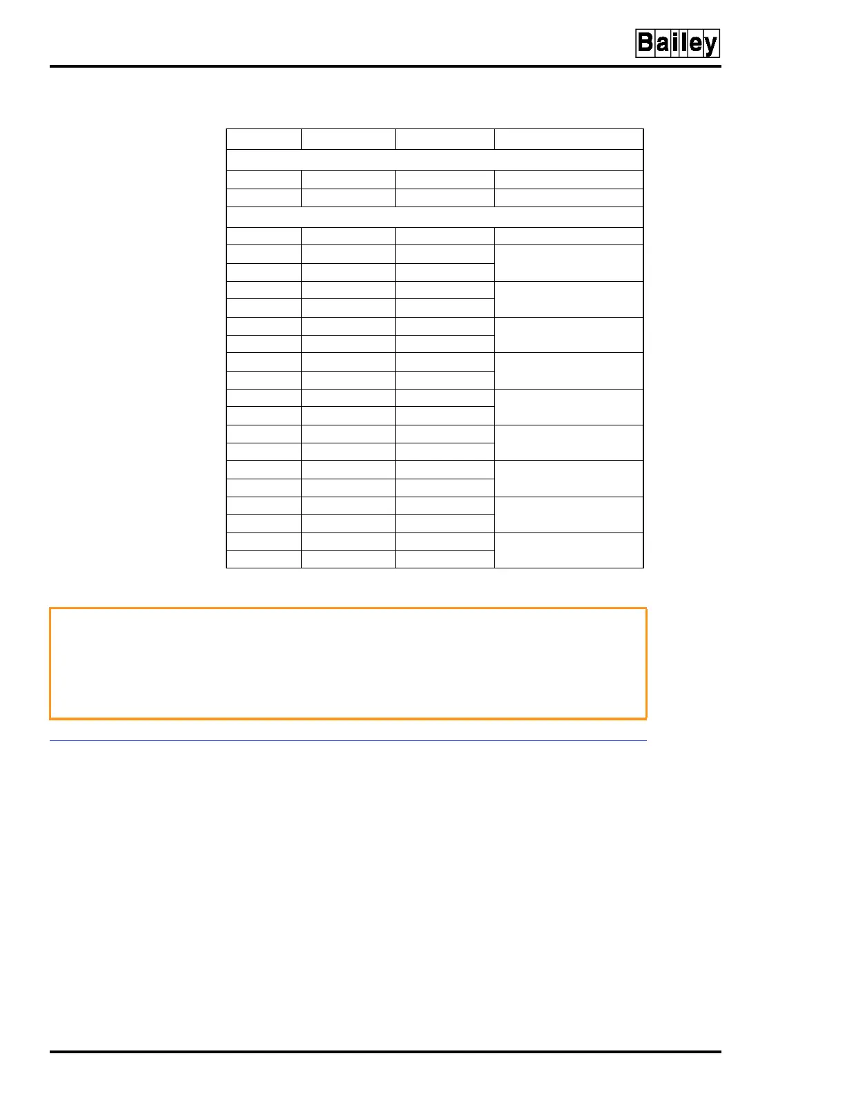
Table 3-3. Switch S4 Normal Mode/Test Mode Settings
Position Open (1 - off) Closed (0 - on) Function
NORMAL MODE-Switch Position 1 is CLOSED
2 X NVRAM initialize.
3 X Configuration lockout.
DIAGNOSTIC MODE-Switch Position 1 is OPEN
2-8 X Group Test
2-7 X Switch/LED Test
8X
2-6,8 X ROM 2 Test
7X
2-6 X ROM 1 Test
7X
2-5,7&8 X RAM Test
6X
2-5,7 X Clock Test
6,8 X
2-5,8 X Hardware Timer Test
6,7 X
2-5 X Analog Output Test
1
6-8 X
2-4,6-8 X Digital Output Test
1
5X
2-4,6&7 X Machine Fault Timer
(MFT) Test
5-8 X
NOTE:
Red LED will light if test fails.
1
WARNING
Do not run these tests while a COM is connected to ANY final
elements. The test produces analog output triangle waveforms
from 0 percent to 100 percent. The digital outputs cycle on and
off continuously.
AVERTISSEMENT French translation to be supplied later.