1-4 Introduction MN762
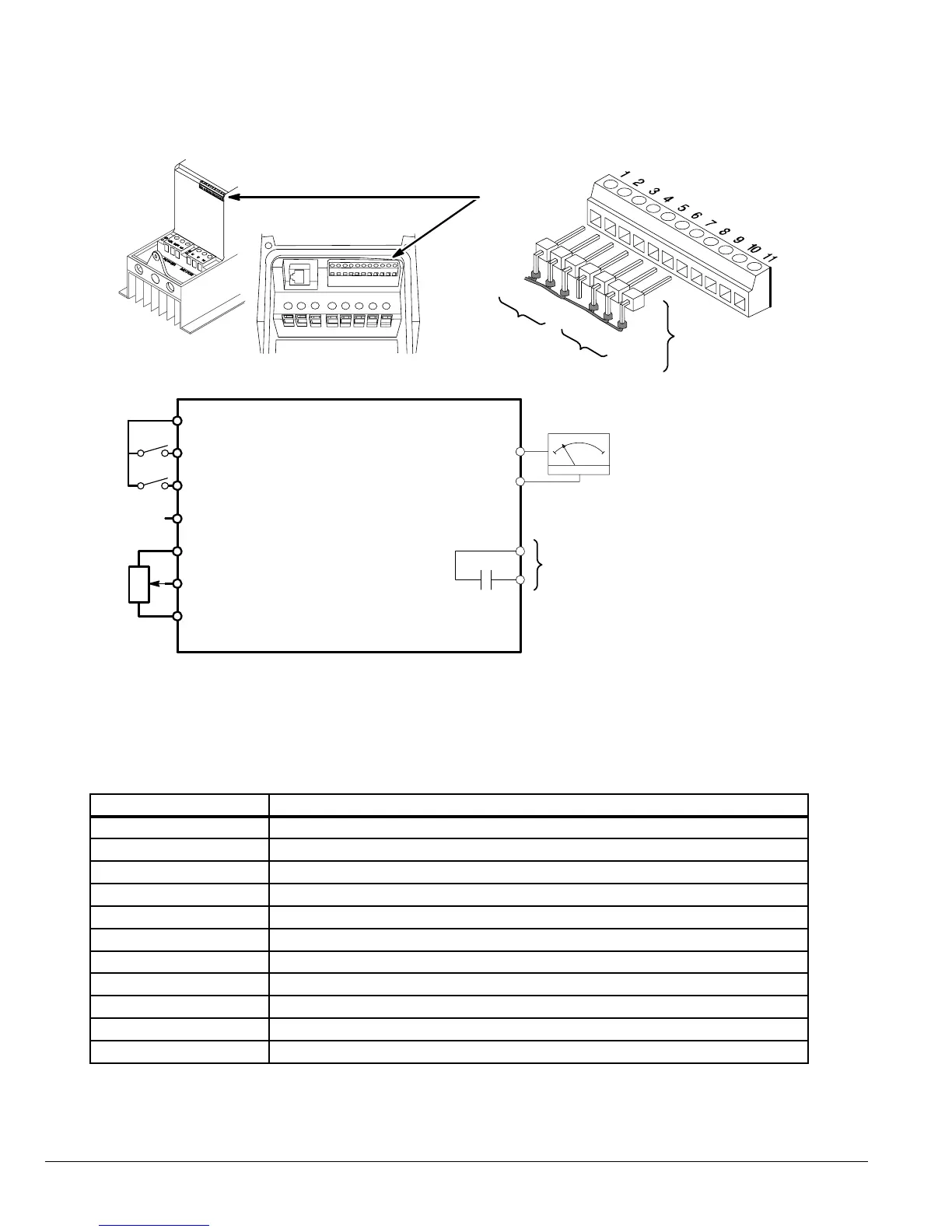
Figure 1-2 Input Connections
Red
Blu
Yel
Grn
Wht
Blk
Front
Panel
Speed Pot
Front
Panel
FWD-O-REV
Switch
1
2
3
4
5
VS1MX
Tightening Torque = 3.5 lb-in (0.4Nm)
+24VDC Reference
Forward (Digital In1)
6
7
Reverse (Digital In2)
Digital In3 / Analog In2
+10VDC POT Reference
Analog In1
Analog Common
Relay Output
10
11
8
9
C ommon
Analog / Digital Output
Analog Output
(0-10 VDC )
* Optional Hardware not provided.
** Only provided in Switched version.
*
Control Wiring
Terminals
Only on
Switched versions
**
**
Table 1-1 Control Terminal Descriptions
Terminal Signal Description
1 +24VDC (@ 100 mA)
2 Digital In1 (8 - 30 VDC)
3 Digital In2 (8 - 30 VDC)
4 Digital In3 (8 - 30 VDC) / Analog In2 (0 - 10 VDC, 0 - 20mA or 4 - 20mA)
5 +10VDC (@ 10 mA) Reference for Potentiometer (1kohm minimum)
6 Analog In1 (0 - 10 VDC, 0 -20mA or 4 - 20mA) / Digital In4 (8 - 30 VDC)
7 Common (terminals 7 & 9 are connected)
8 Analog Output (0-10 VDC @ 20mA max) / Digital Output (0-24 VDC)
9 Common (terminals 7 & 9 are connected)
10 Relay Common
11 Relay N.O. Contact (rated 250VAC@6A; 30VDC@5A)