3-2 Installing the Drive MN762
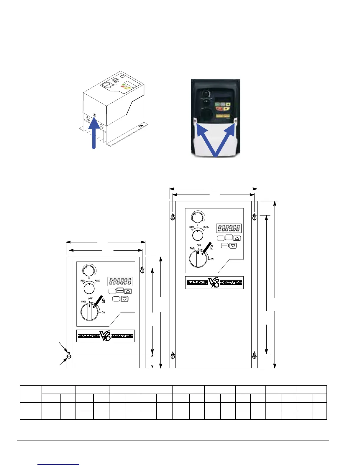
3.4 Cover Removal
To connect power and signal wires, the cover must be removed as shown in Figure 3-1.
Figure 3-1 Cover Removal
Press in (cover release)
then lift cover to remove.
Remove 2 screws then left
the white cover to remove.
Figure 3-2 NEMA 12 / IP55 Mounting Hole Locations
B 1
A1
A
B
A1
A
B 1
I
A2
STOP
RESET
START
PROG
ENT
STOP
RESET
START
PROG
ENT
Table 3-2 NEMA 12 / IP55 Dimensions
Frame
A A1 A2 B B1
I Φ J Φ
C (Depth Weight
in mm in mm in mm in mm in mm in mm in mm in mm lb kg
A 7.87 200 5.55 141 1.30 33 5.51 140 5.04 128 0.17 4.2 0.33 8.4 6.54 166 5.07 2.3
B 12.20 310 9.88 251 1.30 33 6.46 164 6.02 153 0.17 4.2 0.33 8.4 7.09 180 9.92 4.5
Control Terminal Torque Settings of 4.5 lb-in (0.5 Nm)
Power Terminal Torque Settings of 9 lb-in (1 Nm)