3-4 Installing the Drive MN762
3.5 Conduit Size and Lock off
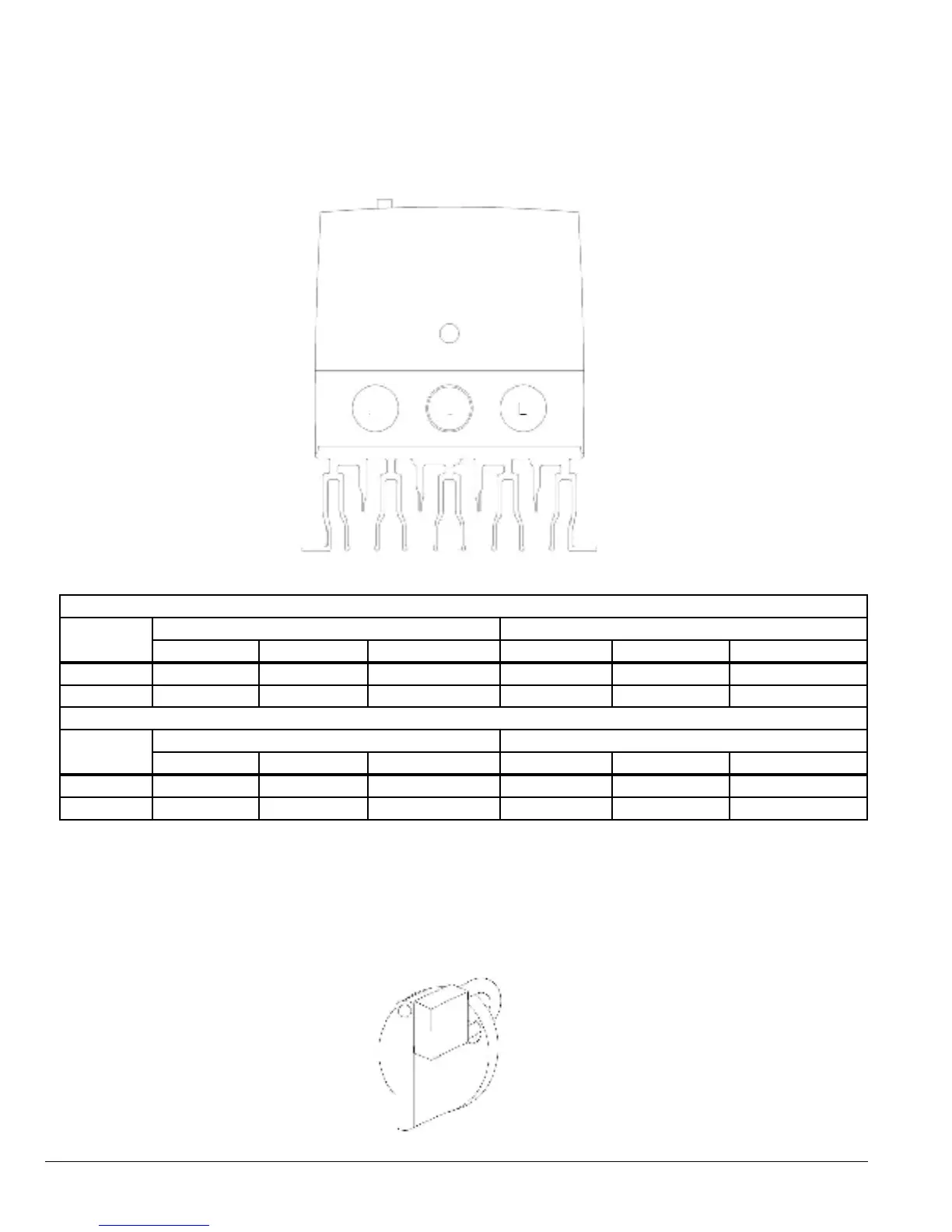
Figure 3-4 Opening Identification
B
A
C
Table 3-4 Opening Dimensions
Cable Gland recommended Hole Sizes and Types:
Frame Size
Opening A and C Knock Out B
Diameter UL Gland Size Metric Gland Size Diameter UL Gland Size Metric Gland Size
A .866 (22mm) PG13.5 M20 .866 (22mm) PG13.5 M20
B & C 1.11 (28.2mm) PG21 M25 .866 (22mm) PG13.5 M20
Flexible Conduit Hole Sizes:
Frame Size
Opening A and C Knock Out B
Diameter UL Gland Size Metric Gland Size Diameter UL Gland Size Metric Gland Size
A .866 (22mm) 3/4 in 28mm .866 (22mm) 3/4 in 21
B & C 1.11 (28.2mm) 1 in 35mm .866 (22mm) 3/4 in 27
Note: UL rated ingress protection (“Type”) is only met when cables are installed using a UL recognized bushing or tting for
a exible-conduit system which meets the required level of protection (“Type”). Not intended for rigid conduit system.
Figure 3-5 Lock-Off (IP55/NEMA 12 Only)
Lock Off:
On the switched models the main power isolator switch can be locked in the “Off” position using a 20mm standard shackle
padlock or the VS1MX-ILOCK kit.
 Loading...


