CE Guidelines C-3MN762
C.7 EMC Wiring Technique
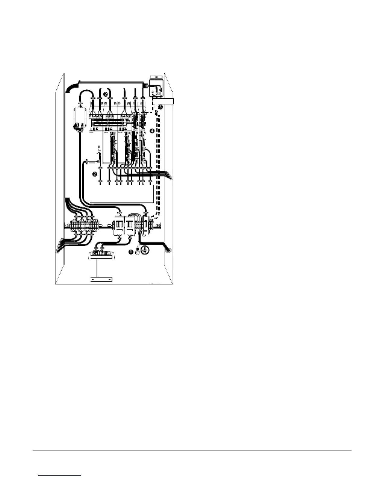
Figure C-2
1 CABINET
The drawing shows an electroplated zinc coated enclosure,
which is connected to ground.
This enclosure has the following advantages:
- All parts mounted on the back plane are connected to ground.
- All shield (screen) connections are connected to ground.
Within the cabinet there should be a spatial separation between
power wiring (motor and AC power cables) and control wiring.
2 SCREEN CONNECTIONS
All connections between components must use shielded cables.
The cable shields must be connected to the enclosure. Use
conductive clamps to ensure good ground connection. With
this technique, a good ground shield can be achieved.
3 EMC - FILTER
The EMI or main lter should be mounted next to the power
supply (here BPS). For the connection to and from the main
lter, screened cables should be used. The cable screens
should be connected to screen clamps on both sides.
(Exception: Analog Command Signal).
4 GROUNDING (EARTH)
For safety reasons (VDE0160), all Baldor components
must be connected to ground with a separate wire. The
diameter of the wire must be at minimum AWG#6 (10mm
2
).
Ground connections (dashed lines) must be made from
the central ground to the regen resistor enclosure and
from the central ground to the Shared Power Supply.
5 Y-CAPACITOR
The connection of the regeneration resistor can cause RFI
(radio frequency interference) to be very high. To minimize
RFI, a Y-capacitor is used. The capacitor should only be
connected between the dynamic brake resistor housing and
terminal pin R1.
CONTROLLER
Y-Capacitor
Attention: The drawing shows only the principle of an EMC wiring. The installation shown can be
different to any national standard (e.g. VDE).
C.8 EMC Installation Instructions
To ensure electromagnetic compatibility (EMC), the following installation instructions should be completed. These steps help
to reduce interference.
Consider the following:
• Grounding of all system elements to a central ground point
• Shielding of all cables and signal wires
• Filtering of power lines
A proper enclosure should have the following characteristics: