10 english
5.2.2 EtherNet/IP interface
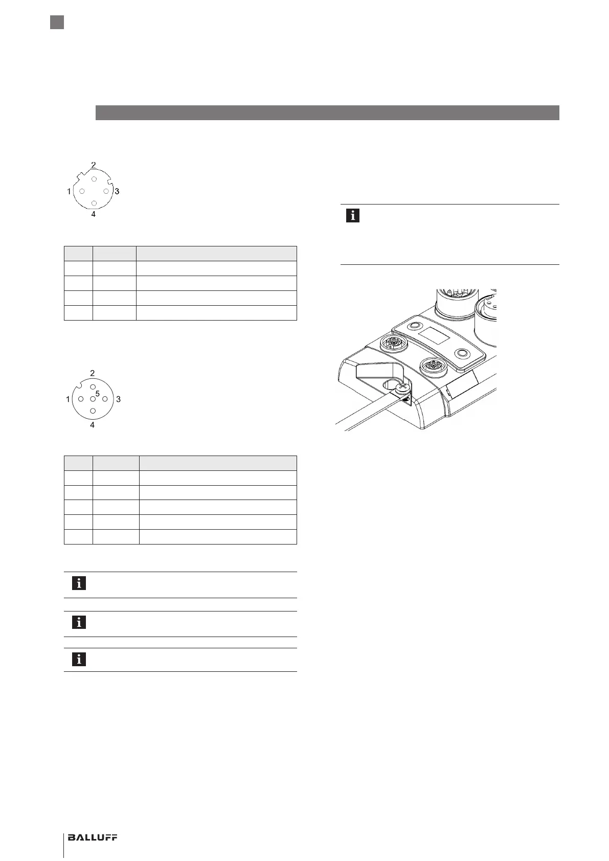
Fig.5-2: Top view of M12 socket, D-coded
Pin Signal Description
1 Tx+ Transmit Data +
2 Rx+ Receive Data +
3 Tx− Transmit Data −
4 Rx− Receive Data −
Tab. 5-2: Pin assignment
5.2.3 I/O-Port
Fig.5-3: Top view of M12 socket
Pin Signal Description
1 US +24V, 2A
2 I/O Input / Output (2A)
3 GND Electrical ground 0V
4 I/O, C/Q Input / Output (2A) / IO-Link
5 n. a. Not available
Tab. 5-3: Pin assignment
For the digital sensor inputs, see the directive on
inputs EN61131-2, type3.
Unused ports must be covered with caps to
ensure IP67 protection.
The IO-Link output is fed from the sensor supply.
5
Installation and connection (continued)
5.2.4 Grounding
To counteract EMC interference, the functional earth
connection must be used.
► Connect the earth terminal to the functional earth (FE)
of the machine.
The FE connection between the housing and
the machine must have a low impedance and
be as short as possible.
► Use the grounding strap included in the
scope of delivery.
Fig.5-4: Ground connection
5.3 Cable routing
Cable length
The Ethernet cable may be max. 100meters long.
The IO-Link single-ended cordset may be max. 20meters
long.
BNI EIP-508- _ 05-Z015- _ _ _
Network interface
 Loading...