www.balluff.com 9english
5.1 Installation
For dimensions, see Fig.4-1 on page7.
► Fasten the module with 2M6 screws and a maximum
tightening torque of 3Nm using the mounting holes
(see Fig.4-2 on page7).
5.2 Electrical connection
Requirements for complying with the protection
classes:
For IP67, all plugs and caps must be properly connected
and the tightening torque of 0.6Nm must be observed
(see data sheets of connectors and caps).
5.2.1 Power supply
NOTICE
Unwanted voltage dips
Non-separated electric circuits of the power supplies for
sensor and actuator can lead to unwanted voltage dips
of the sensor supply when switching actuators.
► Fuse the power supplies for sensors and actuators
separately.
► Make sure that the power supply of the device is
sufficiently dimensioned to cover start-up and peak
currents and design the fuse protection concept
accordingly.
– Establish power supply of sensor/bus and
actuator via a separate power source if possible.
– The total current for the sensor and actuator
supply must not exceed 9A each.
– For UL: Observe cable requirements and power
supply requirements (see chapter8.7.2 on
page14)!
5
Installation and connection
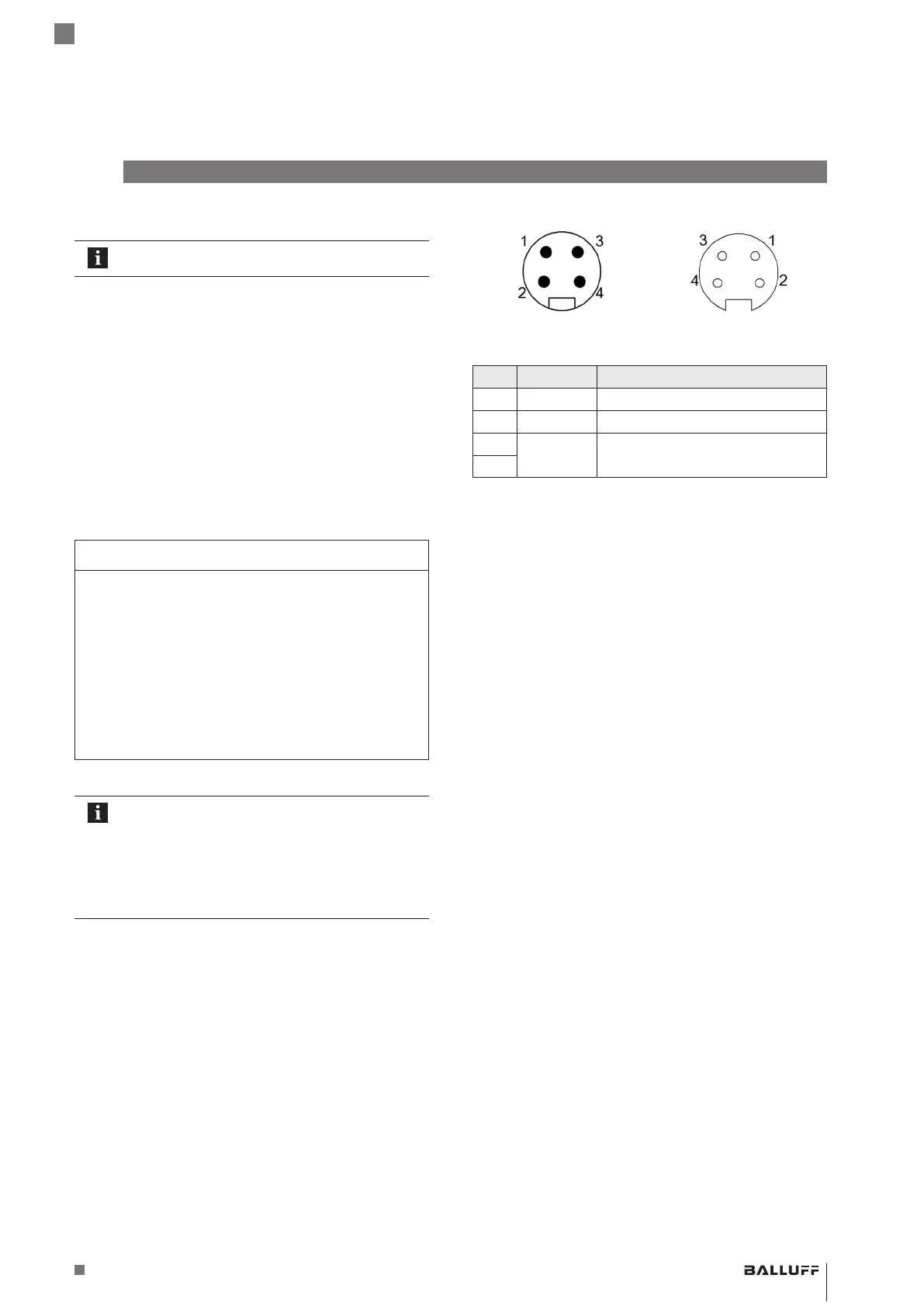
7/8" connector 7/8" socket
Fig.5-1: Top view of 7/8" plug (left) and socket (right)
Pin Signal Description
1 UA Actuator supply +24V
2 US Module/sensor supply +24V
3
GND Common ground
4
Tab. 5-1: Pin assignment
BNI EIP-508- _ 05-Z015- _ _ _
Network interface
 Loading...