Dynamic TEACH and Adaptive Thresholds
• Teach on-the-fly
• Establishes a single switching threshold
• Threshold position is adjustable using “+” and “-” buttons
(Manual Adjust)
Dynamic TEACH is best used when a machine or process may not
be stopped for teaching. It programs the sensor during actual
sensing conditions, taking multiple samples of the light and dark
conditions and automatically setting the threshold at the optimum
level.
Dynamic TEACH activates the sensor’s adaptive threshold system,
which continuously tracks minimum and maximum signal levels,
and automatically maintains centering of the switchpoint between
the light and dark conditions. The adaptive threshold system
remains in effect during Run mode. The adaptive routine saves to
non-volatile memory at least once per hour.
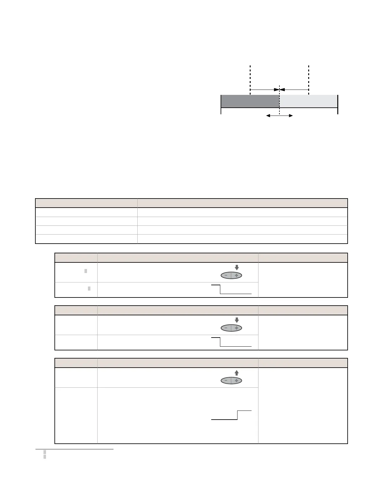
Sensor positions
threshold midway
between taught conditions
Darkest
(no signal)
Most Light
(saturated
signal)
Output OFF Output ON
Darkest Taught
Condition
Lightest Taught
Condition
Position
adjusted by
Manual Adjust
Figure 3. Dynamic TEACH (Light Operate shown)
When Dynamic TEACH mode is used, the output ON state (Light or Dark Operate) remains as it was last programmed. To
change the output ON state, use Setup mode.
Dynamic TEACH and Manual Adjust
The switchpoint may be adjusted (fine-tuned) whenever the sensor is in Run mode by clicking the “+” and “-” buttons.
However, when a manual adjustment is made, the adaptive threshold system is disabled (cancelled).
Bar Graph LED Following TEACH
Relative Signal Difference / Recommendation
6 to 8 Excellent: Very stable operation
4 to 5 Good: Minor sensing variables may affect sensing reliability
2 to 3 Low: Minor sensing variables may affect sensing reliability
1 Unreliable: Consider an alternate sensing scheme
1. Access the Dynamic TEACH Mode.
Method
Action Result
Push Button
4
Press and hold the Dynamic push button > 2
seconds.
• Power LED: OFF
• Output LED: OFF
• Bar graph: LO & DO alternately
flash
Remote Input
5
Hold the remote line low (to ground) > 2 seconds.
2. TEACH the sensing condition.
Method
Action Result
Push Button
Continue to hold push button and present Output
ON and OFF conditions.
• Power LED: OFF
• Output LED: OFF
• Bar graph: LO & DO alternately
flash
Remote Input
Continue to hold remote line low (to ground) and
present Output ON and OFF conditions.
3. Return to RUN Mode.
Method
Action Result
Push Button Release the push button.
TEACH Accepted
• Power LED: ON
• Bar graph: One LED flashes to
show relative contrast (good
signal difference shown; see
table above)
Sensor returns to Run mode with new
settings.
TEACH Not Accepted
• Power LED: OFF
• Bar graph: #1, 3, 5, 7
alternately flash to show failure
Sensor returns to Run mode without
changing settings
Remote Input Release the remote line/switch
4
0.04 seconds ≤ "Click" ≤ 0.8 seconds
5
0.04 seconds ≤ T ≤ 0.8 seconds
D10 Expert
™
Series with Bar Graph Display and Discrete Output
4 www.bannerengineering.com - Tel: +1-763-544-3164 P/N 117830 Rev. G

 Loading...