111R5914712 /00 SP2K-C
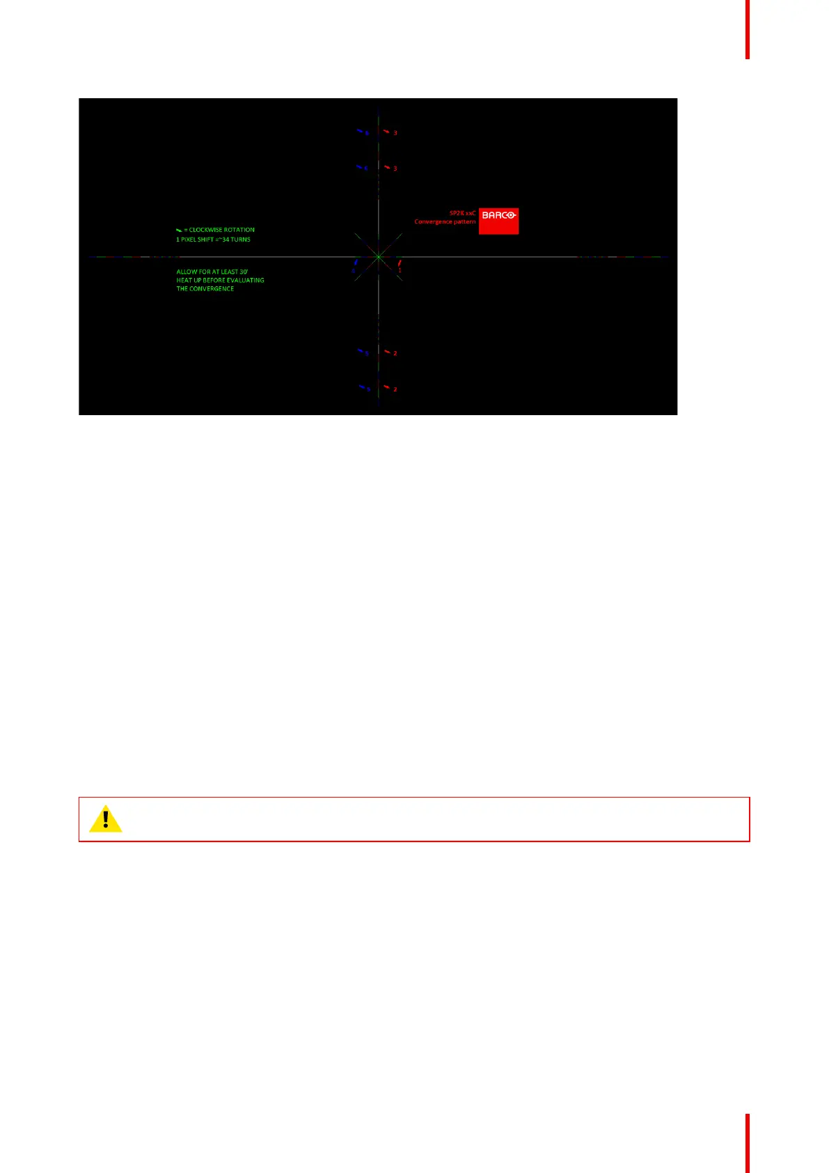
Image 10–8
The previously illustrated test pattern is specifically designed for convergence purposes on this projector. The
test pattern has three red arrows numbered from 1 to 3 and three blue arrows numbered from 4 to 6. These
numbers and colors correspond to those of the control knobs. Each knob is marked with an arrow which
corresponds to the direction indicated on the screen.
Basic instructions
Keep into account the following:
• BLUE and RED DMD’s are to be adjusted with reference to the GREEN DMD.
• Each adjustment allows for 6–8 pixels maximum displacement to either side of the nominal GREEN
position.
• Rotation is limited to 2–3 pixels on the left and on the right screen flank.
• 1 pixel displacement on the screen relates to 34 full turns of an adjustment screw.
• Before starting to adjust the convergence, let the projector warm up for at least 1 hour, while projecting the
convergence test pattern and while using the correct brightness level.
Adjustment Range
Avoid slipping of the torque limiter clutch by limiting the amount/number of adjustment(s) made. Typically the
convergence adjustments serve to correct a convergence fault of a few pixels at the most. Any convergence
fault beyond this is considered grossly abnormal and likely indicates abuse or rough handling. However, in
extreme cases correction of up to five pixels is possible.
CAUTION: The system does have an end of travel in either direction, but using excessive force may
cause damage. Please handle gently.
Convergence