R5914712 /00 SP2K-C110
10.3 Convergence controls
Control knobs
As the DMD of the green channel is not accessible in the projector, it remains fixed. Therefore the image of
this DMD will be taken as reference. Red and Blue will be aligned onto green when a small convergence drift
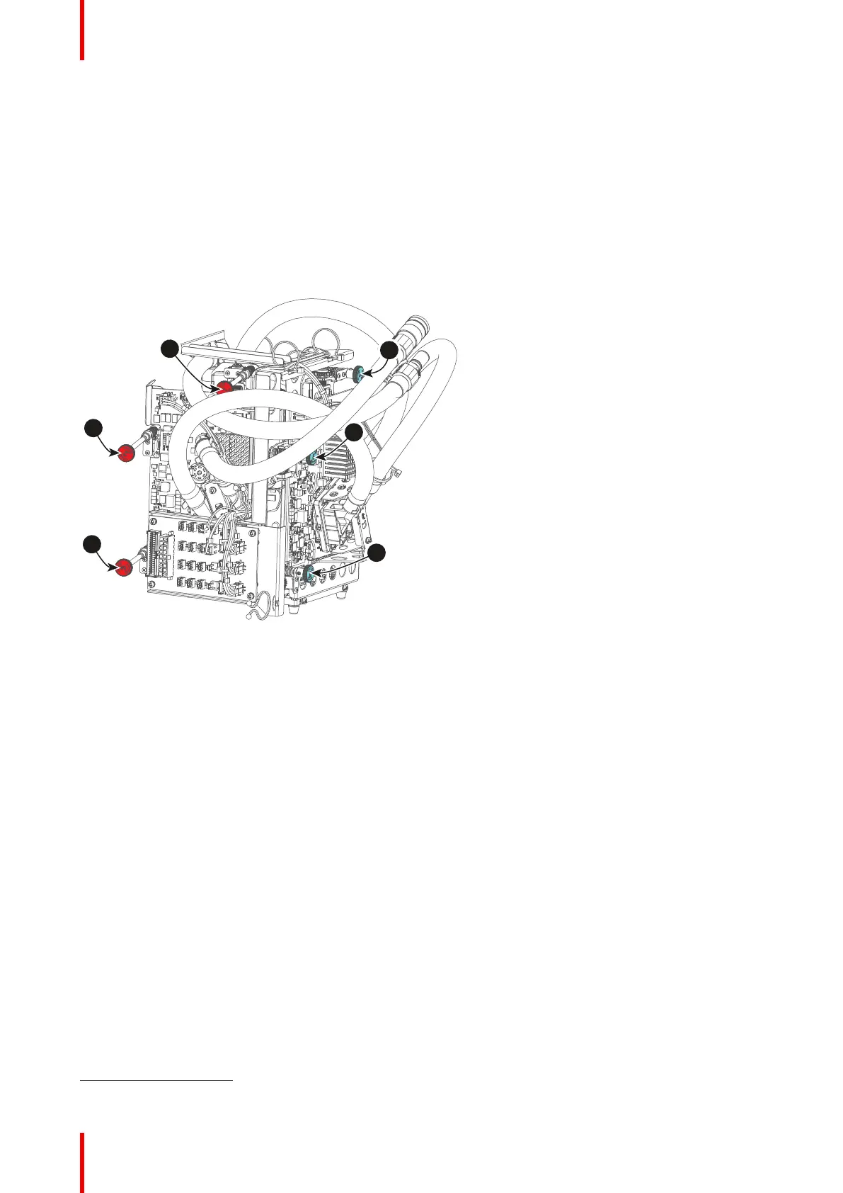
is recognized. The red and blue channels have pivot plates equipped with three control knobs for convergence
adjustment, of which the red ones are extended. The adjustment knobs are numbered from 1 to 6 and have
the same color as the channel which they affect.
To access the control knobs, the top cover and left side cover of the projector must be removed, as well as the
top cover plate and side cover plate of the Light Processor compartment.
Image 10–7
1 Red channel, knob number 1
5
2 Red channel, knob number 2
5
3 Red channel, knob number 3
5
4 Blue channel, knob number 4
5 Blue channel, knob number 5
6 Blue channel, knob number 6
Convergence test pattern
For the manual correction of the DMD convergence a typical convergence test pattern is generated. Select the
test pattern labeled Convergence_pattern_SP2K-xxC.
Convergence
5. Exact position of the knobs can differ slightly