AW00118508000 Physical Interface
Basler racer Camera Link 34
5.2 Camera Connector Pin Assignments
and Numbering
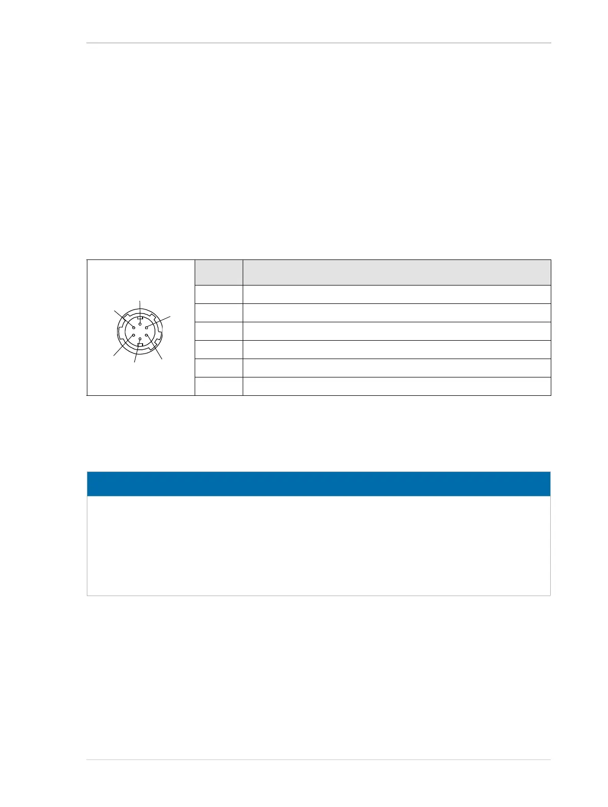
5.2.1 6-pin Receptacle
The 6-pin receptacle is used to supply power to the camera. The pin assignments and pin
numbering for the receptacle are as shown in Table 6.
* Pins 1 and 2 are tied together inside of the camera.
** Pins 5 and 6 are tied together inside of the camera.
Pin Designation
1 +12 VDC (-10 %) to +24 VDC (+5 %), < 1 % ripple, camera power *
2 +12 VDC (-10 %) to +24 VDC (+5 %), < 1 % ripple, camera power *
3 Not connected
4 Not connected
5 DC ground **
6 DC ground **
Table 6: Pin Assignments and Numbering for the 6-pin Receptacle
NOTICE
Applying incorrect power can damage the camera.
The camera‘s required operating voltage is +12 VDC (-10 %) to +24 VDC (+5 %), effective
on the camera‘s connector.
Applying power with the wrong polarity can severely damage the camera.
Make sure that the polarity of the power applied to the camera is correct.