AW00118508000 Physical Interface
Basler racer Camera Link 37
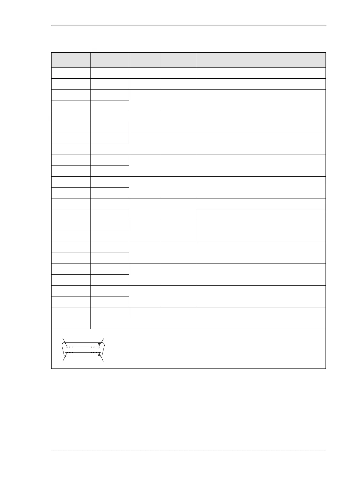
Pin Number Signal Name Direction Level Function
1, 26 * Cam Pow. In Not used
13, 14 ** Power Ret. Return Gnd
2 Y0- Output Camera Link
LVDS
Data from transmitter circuit Y
15 Y0+
3 Y1- Output Camera Link
LVDS
Data from transmitter circuit Y
16 Y1+
4 Y2- Output Camera Link
LVDS
Data from transmitter circuit Y
17 Y2+
6 Y3- Output Camera Link
LVDS
Data from transmitter circuit Y
19 Y3+
5 YClk- Output Camera Link
LVDS
Pixel clock from transmitter circuit Y
18 YClk+
7 T+ Connected to T- with 100R; not used
20 T- Connected to T+ with 100R; not used
8 Z0- Output Camera Link
LVDS
Data from transmitter circuit Z
21 Z0+
9 Z1- Output Camera Link
LVDS
Data from transmitter circuit Z
22 Z1+
10 Z2- Output Camera Link
LVDS
Data from transmitter circuit Z
23 Z2+
12 Z3- Output Camera Link
LVDS
Data from transmitter circuit Z
25 Z3+
11 ZClk- Output Camera Link
LVDS
Pixel clock from transmitter circuit Z
24 ZClk+
* Pins 1 and 26 are tied together in the camera.
** Pins 13 and 14 are tied together in the camera.
Table 8: Pin Assignments and Numbering for the Medium/Full Configuration 26-pin SDR Connector