AW00118508000 Acquisition Control
Basler racer Camera Link 70
Exposure Start and Exposure End Delays
When the trigger mode is set to On and an input line is selected as the source signal for the line
start trigger, there is a delay between the transition of the line start signal and the actual start of
exposure. For example, if you are using the timed exposure mode with rising edge triggering, there
is a delay between the rise of the signal and the actual start of exposure.
There is also an exposure end delay, i.e., a delay between the point when exposure should end as
explained in the diagrams on the previous page and when it actually does end.
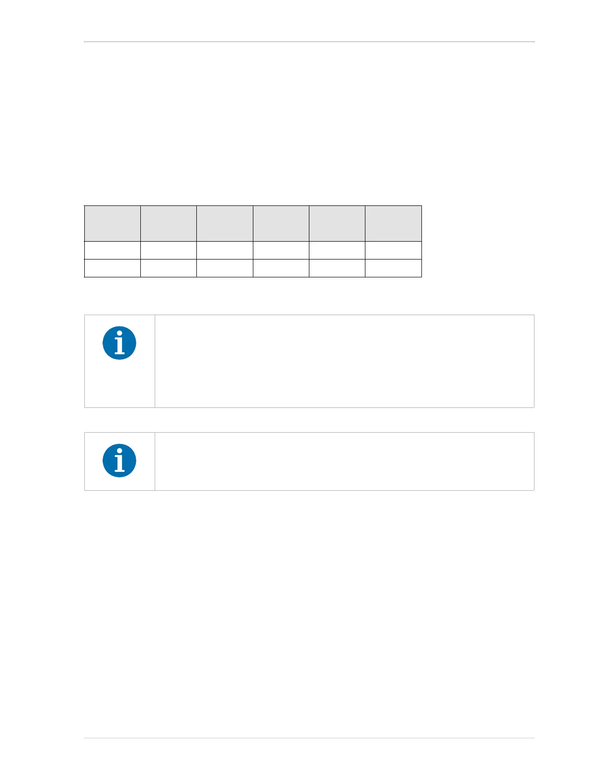
The base exposure start and end delays are as shown in Table 13:
There is also a second component to the start and end delays. This second component is the
debouncer setting for the input line. The debouncer setting for the input line must be added to the
base start and end delays shown in Table 13 to determine the total start delay and end delay.
For example, assume that you are using an raL2048-80km camera and that you have set the trigger
mode to On. Also assume that you have selected input line CC1 as the source signal for the line
start trigger and that the debouncer parameter for line CC1 is set to 5 µs. In this case:
Total Start Delay = Start Delay Value from Table 13 + Debouncer Setting
Total Start Delay = 1.5 µs + 5 µs
Total Start Delay = 6.5 µs
Total End Delay = End Delay Value from Table 13 + Debouncer Setting
Total End Delay = 1.2 µs + 5 µs
Total End Delay = 6.2 µs
raL2048-
80km
raL4096-
80km
raL6144-
80km
raL8192-
80km
raL12288-
66km
Start Delay 1.5 µs 1.5 µs 1.5 µs 1.5 µs 1.5 µs
End Delay 1.2 µs 1.2 µs 1.2 µs 1.2 µs 1.2 µs
Table 13: Base Exposure Start and End Delays
If you are using a GenICam compliant tool such as the Basler pylon Viewer and
you attempt to set the exposure time to exactly the minimum allowed or to exactly
the maximum allowed, you will see unusual error codes. This is an artifact of a
rounding error in the GenICam interface architecture. As a work around, you could
set the exposure time slightly above the minimum or below the maximum. Values
between the minimum and the maximum are not affected by the problem.
When using the frequency converter, the delay values may slightly differ from
those given in Table 1 3 . For more information about the frequency converter, see
Section 6.3 on page 80.