Baumer_EAM580_360_SAE_J1939_MA_EN_Rev0003.0000h_Index0002.docx Baumer Electric AG
06.08.2018 11/27 Frauenfeld, Switzerland
5 CAN Frame
A standard CAN-Frame with a 29-Bit identifier is being used for the J1939 bus. The data in the PDU fields will be
interpreted differently, depending on choosen PDU1 or PDU2 format, which is defined by the Identifier.
5.1 Identifier
The Identifier is defined as the CAN 29-Bit Identifier and can be configured by the user in two ways:
Configuring of default ECU address (Object 0x2102)
Configuring of Group Extension (Object 0x2103)
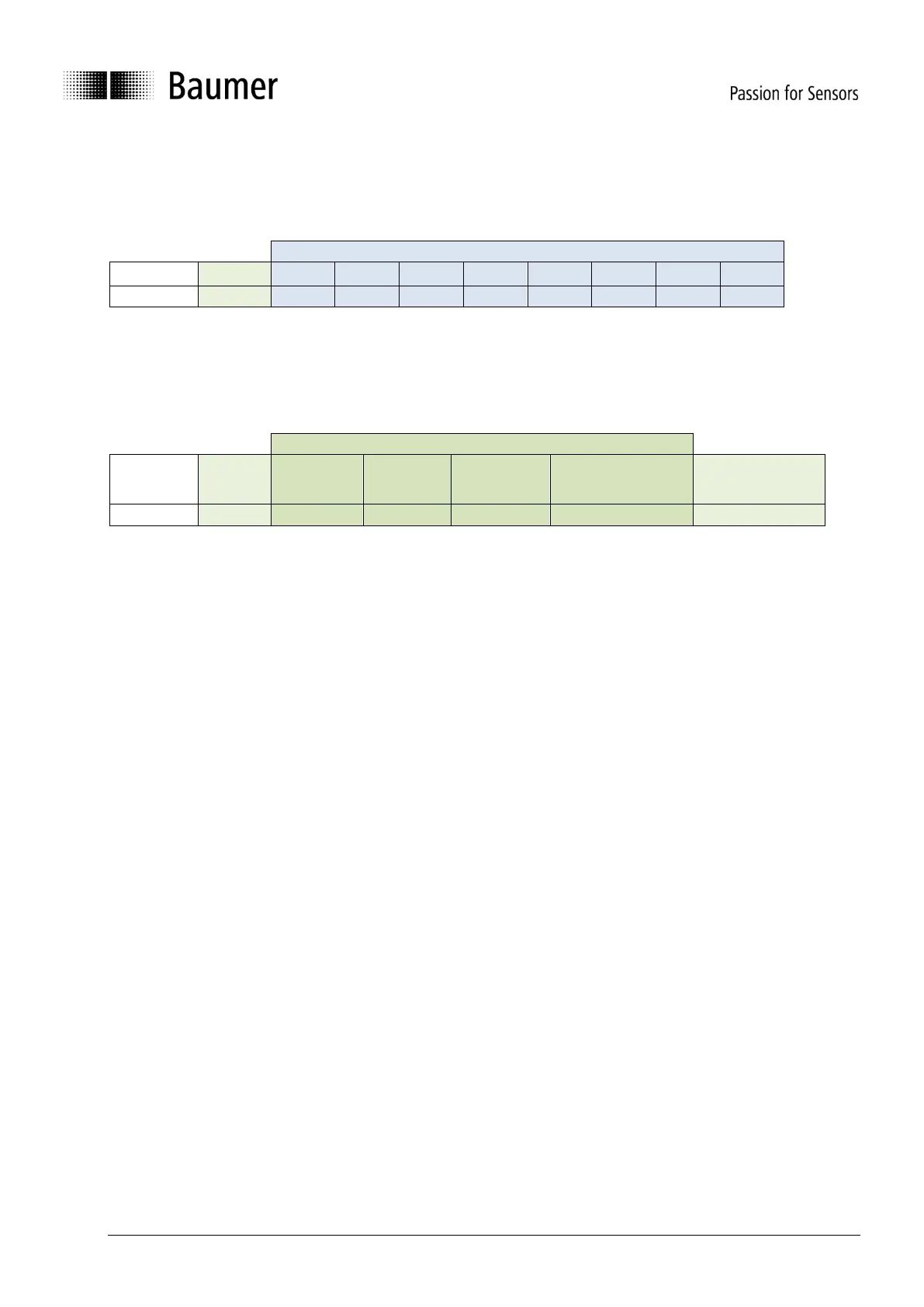
Parameter Group Number (PGN)
Destination Address
Group extension
Source address
(ECU address)
Principally, there are two different message formats used in the J1939 protocol, which are defined by the data range of
the PDU format field:
PF Values 0 … 240 (called as PDU1 Format)
Peer-to-Peer and broadcast communication
Field Destination Address always contains the receivers address, or broadcast (25%)
Used for Encoder parametrization
PF Values 240 … 255 (called as PDU2 Format)
Only broadcast communication
Field Destination Address is used as Group Extension value
Used for cyclic sending values of the Encoder
As lower the value, as higher is the priority on the bus.
This value is fixed to the value 6.
Only value 0 is supported
Only value 0 is supported
If Values < 0xEF -> PDU1 format is used
If Values > 0xFE -> PDU2 format is used
PDU1: Destination Address:
PDU2: Group Extension:
PDU1: This is either the address of the Encoder,
when requesting data or this will be the address of
the ECU, which requested Data, when the
Encoder responds to a message.
PDU2: Group Extension, can used to create an
offset to the cyclic message PGN (65450 + Group
Extension)
Source address
(ECU address)
Containing always the own address (default-value: 172).
This address is claimed with the NM Service (see address
claiming)