Baumer_EAM580_360_SAE_J1939_MA_EN_Rev0003.0000h_Index0002.docx Baumer Electric AG
06.08.2018 10/27 Frauenfeld, Switzerland
4.3.5 Electronic gear function
The electronic gear function divides the position value by the gear factor. Therefore it transforms the position value into
the view of the application:
𝑎𝑝𝑝𝑙𝑖𝑐𝑎𝑡𝑖𝑜𝑛 𝑝𝑜𝑠𝑖𝑡𝑖𝑜𝑛 =
𝑒𝑛𝑐𝑜𝑑𝑒𝑟 𝑝𝑜𝑠𝑖𝑡𝑖𝑜𝑛
𝑖
The gear factor (i) is defined as followed:
𝑖 =
𝐺𝑒𝑎𝑟𝑉𝑎𝑙𝑢𝑒1
𝐺𝑒𝑎𝑟𝑉𝑎𝑙𝑢𝑒2
There are three objects that should be configured to use the electronic gear function.
0x2001-1 Enable
Set this object to the value “2” to enable the electronic gear function, while the value “1” disable it.
0x2001-2 Gear Value 1
This Object defines the numerator of the gear factor.
The range of this integer value is 1…32767.
0x2001-3 Gear Value 2
This Object defines the denominator of the gear factor.
The range of this integer value is 1…32767.
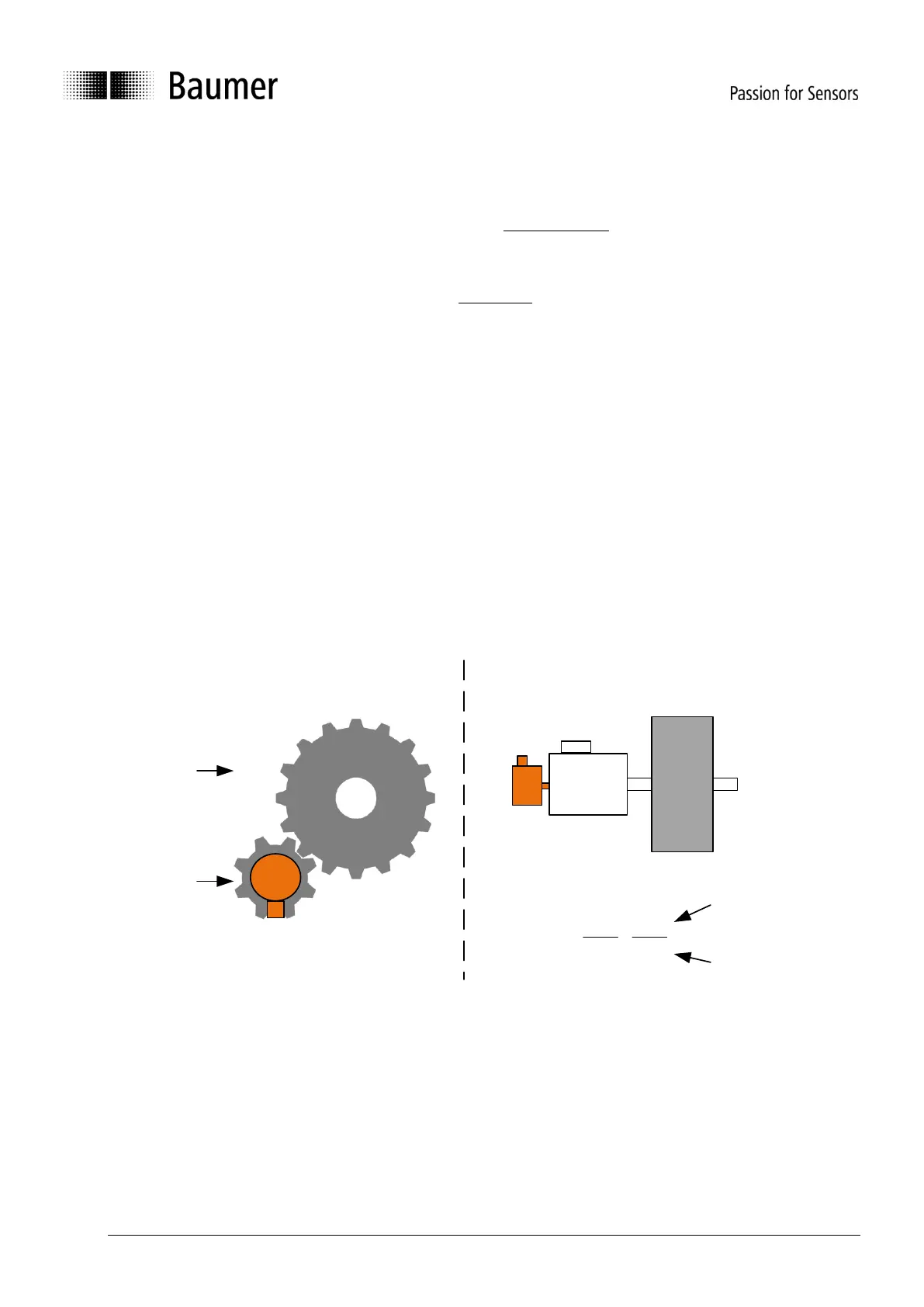
Figure 1: Example configuration of gear values
obj 2001h-3h
GearValue2
eg. 8 teeth
Example
discrete gear with number of teeth
obj 2001h-2h
GearValue1
eg. 17 teeth
Motor
Gear
gear ratio i
=
6.25
1
=
625
100
obj 2001h-2h
GearValue1
eg. 625
obj 2001h-3h
GearValue2
eg. 100
i = 6.25
Example
gear box
Encoder
Encoder
Application
Application
Limitations
A useful gear ratio is greater than 0.125, while a gear ratio smaller than 1 may result in higher signal noise.
The maximum encoder turns in unpowered operation must be smaller than 2
29
(536’870’912) turns.
The electronic gear function is useful for multiturn encoders. In case of singleturn encoders, the position value gets lost
after a power cycle.
4.4 Encoder as standard component with embedded software used in safety functions
If this standard encoder is used in safety functions, please request the according “Application Note MAGRES EAM” for
further information.