EasyManua.ls Logo

Baumer NE212 User Manual

Baumer NE212
64 pages
Go to English
To Next Page IconTo Next Page
Page #1 background imageLoading...
Page #1 background image
08.15
171.51.306/5
81005196
Irrtum sowie Änderungen in
Technik und Design vorbehalten.
Subject to modifcation in technic & design.
Inhalt
1 Allgemeines / Sicherheitshinweise
2 Systembeschreibung
2.1 Beschreibung
2.2 Blockdiagramm
3 Gerät anschliessen
3.1 Betriebsspannung anschliessen
3.2 Signalausgänge „Relaiskontakte
3.3 Elektronische Ausgänge belegen
3.4 Signaleingänge belegen
3.4.1 Anschlussbeispiele
3.5 Sensorversorgung anschliessen
3.6 Schnittstellen anschliessen
3.7 Testroutine durchführen
4 Bedienerebene
5 Programmierebene
5.1 Betriebsarten Hauptzähler
5.2 Zählweise (Input modes)
5.3 Ausgangsverhalten (Output modes)
6 Technische Daten
6.1 Abmessungen
6.2 Werkseinstellungen
6.3 Fehlermeldungen
7 Bestellbezeichnung
Baumer IVO GmbH & Co. KG
Dauchinger Strasse 58-62
DE-78056 Villingen-Schwenningen
Phone +49 7720 942-0
Fax +49 7720 942-900
www.baumer.com
info.de@baumerivo.com
Betriebsanleitung
Elektronischer Vorwahlzähler
NE212
Contents Seite / Page
General / Safety instructions 2 / 34
System description 4 / 36
Description 4 / 36
Block diagram 5 / 37
Connecting 6 / 38
Connecting the power supply 8 / 40
Assignment signal output „relay“ 8 / 40
Assignment electronic output 9 / 41
Assignment signal input 9 / 41
Typical connections 11 / 43
Connecting the sensor supply 11 / 43
Connecting the interfaces 12 / 44
Executing the test routine 13 / 45
Operating mode 14 / 46
Programming mode 16 / 48
Operating modes 25 / 57
Counting modes (input modes) 25 / 57
Output responses (output modes) 26 / 58
Technical data 29 / 61
Dimensions 31 / 63
Default settings 31 / 63
Error messages 32 / 64
Part number 32 / 64
Operating Instructions
Electronic preset counter
NE212
Question and Answer IconNeed help?

Do you have a question about the Baumer NE212 and is the answer not in the manual?

Baumer NE212 Specifications

General IconGeneral
BrandBaumer
ModelNE212
CategoryCash Counter
LanguageEnglish

Summary

Safety Instructions

Explanation of Symbols

Explains the meaning of symbols used in the manual for clarity.

General Safety Information

General safety precautions and information for operating the units safely.

Proper Use Guidelines

Guidelines for the intended application and operation of the units.

Installation and Maintenance Safety

Safety guidelines for installation, commissioning, and maintenance, including handling defective units.

System Description

Product Description

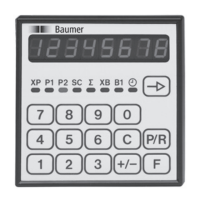
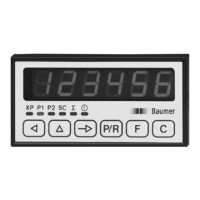
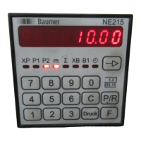
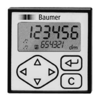
Overview of the electronic preset counter's functions and types.

LED Symbol Display

Explanation of the LED indicators used for status and information display.

Control Panel and Block Diagram

Description of the control panel layout and the system's block diagram.

Counter Connection

Connecting Voltage Supply

Instructions for connecting the power supply, including voltage options and protection.

Signal Output Relay Contact Assignment

Details on assigning signal outputs for relay contacts and their specifications.

Electronic Output Assignment

Information on programming and assigning electronic outputs as NPN or PNP.

Signal Input Assignment

Guide to assigning signal inputs, including specifications for different input types.

Typical Connections and Sensor Supply

Examples of typical connections and instructions for connecting the sensor supply.

Connecting the Interface

Information on connecting serial interfaces like RS232, RS422, and RS485.

Executing the Test Routine

Procedure for running and testing the counter's functions, including keyboard, input, and output tests.

Operating Mode

Key Functions and Parameter Input

Overview of key operations and how to input parameters in operating mode.

Main Counter Status and Preset Values

Reading and changing the main counter status and preset values (P1, P2).

Main Counter Start Count Value

Reading and changing the main counter's start count value.

Totalizing and Batch Counter Operations

Reading, resetting, and changing values for totalizing and batch counters.

Time Meter Operations

Reading and resetting the time meter.

Rapid Preset Value Input with F-key

Using the F-key for quick changes to preset values.

Programming Mode

Programming Fields Overview

Introduction to the four programming segments and their purposes.

Accessing Programming Mode

Steps to enter the programming mode, including code entry and error handling.

Programming Field 1: Parameter Settings

Details on setting operating parameters for counter status, presets, and time meter.

Programming Field 2: Status Selection

Setting access levels (status numbers) for operating parameters.

Programming Field 3: Modes, Frequencies, and Counting

Configuring operating modes, scaling factors, frequencies, and counting modes.

Programming Field 3: Reset, Output Time, and Presets

Setting reset functions, output times for P1, P2, B1, and preset acceptance.

Programming Field 3: Function Key and Special Settings

Configuring function key addresses, batch counter functions, time measurement, and input functions.

Programming Field 4: Interface Configuration

Setting interface parameters like baud rate, parity, address, and stop bits.

Technical Data

Electrical Ratings

Specifications for voltage supply, power consumption, sensor supply, and display.

Mechanical Design and Trigger Levels

Dimensions, housing, materials, weight, and specifications for inputs/outputs.

Dimensions and Default Settings

Physical dimensions and factory programmed default parameter values.

Error Messages

List of error codes and their meanings for troubleshooting.

Part Number

Part Number Configuration

Guide to selecting part numbers based on supply voltage, outputs, and interface.

Related product manuals