EasyManuals Logo

Baxi Power HT Series User Manual

Baxi Power HT Series
Go to English
112 pages
To Next Page IconTo Next Page
To Previous Page IconTo Previous Page
Page #34 background imageLoading...
Page #34 background image
34
910.001.1 - IT
ISTRUZIONI DESTINATE ALL’INSTALLATORE
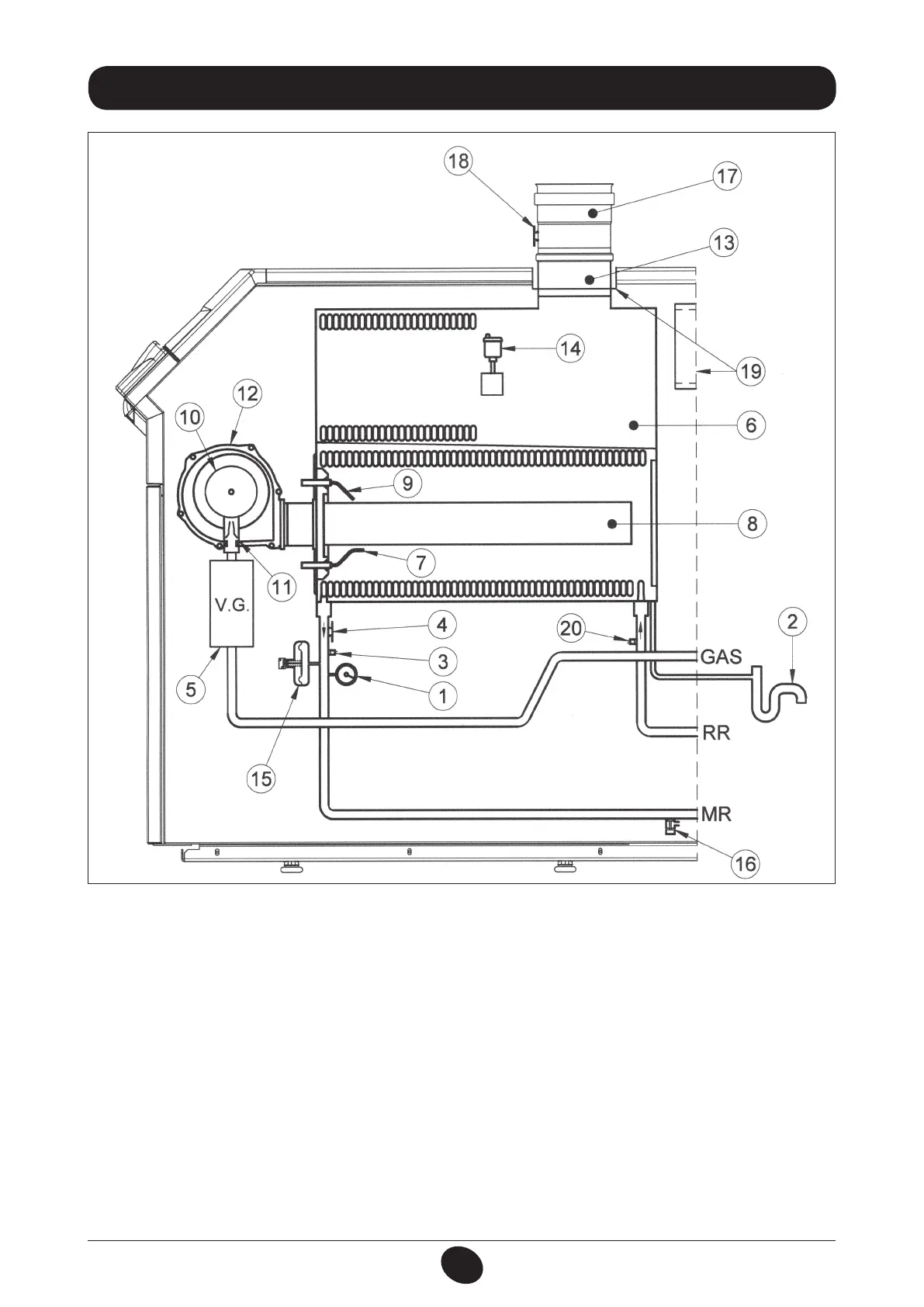
20. SCHEMA FUNZIONALE CIRCUITI
Figura 17
CT_0824 / 0912_1201
Legenda:
1 manometro
2 sifone
3 sonda NTC mandata riscaldamento
4 termostato di sicurezza 105°C
5 valvola del gas
6 scambiatore acqua-fumi
7 elettrodo di rilevazione di fiamma
8 bruciatore
9 elettrodo di accensione
10 mixer con venturi
11 diaframma gas
12 ventilatore
13 raccordo scarico fumi scambiatore
14 valvola automatica sfogo aria
15 pressostato idraulico
16 rubinetto scarico caldaia
17 raccordo scarico fumi con termostato fumi
18 termostato fumi
19 sede condotto aspirazione aria comburente
20 sonda NTC ritorno riscaldamento

Table of Contents

Questions and Answers:

Question and Answer IconNeed help?

Do you have a question about the Baxi Power HT Series and is the answer not in the manual?

Baxi Power HT Series Specifications

General IconGeneral
ModelPower HT Series
TypeCondensing Boiler
InstallationWall-mounted
Heat Exchanger MaterialStainless Steel
Fuel TypeNatural Gas / LPG
Modulation Ratio1:10
Ignition TypeElectronic
Safety FeaturesFlame Failure Protection
NOx EmissionsLow NOx

Related product manuals