97
910.001.1 - EN
ISTRUCTIONS PERTAINING TO THE INSTALLER
Fit the hot water tank after the hydraulic header.
Connect the pump of the external DHW boiler to terminals 13-14 on terminal block M3 (gure 9).
Make sure that the pump has the following specications:
230 V AC; 50 Hz; 1 A max; cos ϕ > 0.8.
If the specications of the installed pump are different, a relay must be wired between the boiler control circuit
board and the pump.
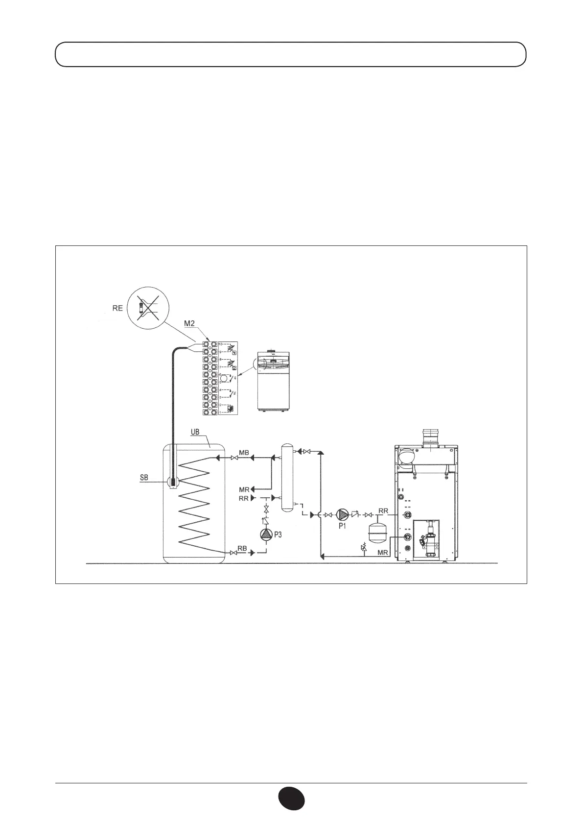
Remove the resistor from terminals 9-10 of terminal block M2 (gure 11), and connect the domestic hot water
priority NTC sensor, which is supplied as an accessory.
The sensing element of the NTC device must be located in the pocket provided on the storage tank (gure 11).
The temperature and on-off programming of the domestic hot water supply are selected directly from the boiler
control panel, as described in this manual under the user instruction headings.
12.7 DOMESTIC HOT WATER CIRCUIT ELECTRIC PUMP CONNECTIONS
If the installation is divided into zones, a relay has to be de-activated to switch off power to the zone pumps,
as shown in the diagram in gure 10.
Figure 11
DHW BOILER CONNECTION DIAGRAM
LEGEND:
UB-D.H.W.STORAGETANK
M2 - TERMINAL BOARD
SB - D.H.W. PRIORITY SENSOR
RE - RESISTOR TO BE REMOVED
MR - CENTRAL HEATING FLOW
RR-CENTRALHEATING/DHWRETURN
MB - D.H.W. STORAGE TANK FLOW
RB-D.H.W.STORAGETANKRETURN
P1-CENTRALHEATINGPUMP
P2-D.H.W.STORAGETANKPUMP
TS - SAFETY THERMOSTAT
PS-SAFETYPRESSURESWITCH
CT_0808 / 0902_2503
 Loading...


